


05/04/16
Overview
The traffic/collision avoidance system (TCAS) is an auxiliary air traffic control (ATC) system. The standard system, TCAS 2000, operates with TCAS I, TCAS II, MODE-S, and ATC-radar-beacon systems (ATCRBS) (i.e. Mode-A, Mode-C). The traffic collision avoidance system (TCAS II) consists of a TCAS computer unit, a top-mounted directional antenna and a bottom-mounted omnidirectional antenna.
The TCAS uses the aircraft's transponder system to monitor an area of three dimensions around the aircraft (the TCAS area). The pilot sets the TCAS area as necessary for the given flight conditions. The TCAS II system provides aural and visual alerts to avoid midair collisions with other aircraft. The system interrogates other aircraft with Modes C and S transponders, tracks their responses and provides advisories to the flight crew to ensure proper vertical separation. The TCAS cannot monitor an aircraft that does not have a transponder. TCAS II is a vertical only system. Intruder bearing displayed on the MFD is not used in the computation of the escape maneuver but enables the flight crew to locate the aircraft visually.
The TCAS is responsible for estimating the projected intruder track and determining if it is a potential conflict. An aircraft that is not transponder-equipped is invisible to TCAS.
The radio management system controls all TCAS functions through an interface with the ATC transponder system. The TCAS 2000 also operates with the airborne data-link system.

05/04/16
TCAS
The airborne collision avoidance system (ACAS) TCAS 2000 system determines the range, altitude, and bearing of other mode C or mode S transponder-equipped aircraft, with respect to the location of own aircraft. It also monitors the trajectory of these aircraft to determine if any of them constitute a potential collision hazard. The TCAS 2000 is a TCAS II with change 7/ACAS II (ACAS II, which is the European equivalent to TCAS II with Change 7.0) system. The TCAS is responsible for estimating the projected intruder track and determining if a potential conflict exists. If so, the system displays an advisory to the pilot. The system also provides guidance for the optimum vertical avoidance maneuver. It transmits interrogations (the range and altitude data) at 1,030 MHz and receives interrogations at 1,090 MHz.
Complementary avoidance maneuvers between two TCAS-equipped aircraft are ensured by coordination of mutual intentions with the other aircraft through the mode S transponders. The TCAS does not contain display or voice output devices, it supplies its outputs through other avionics systems. Thus, the TCAS transmits its display data to the electronic flight-instrument system (EFIS). The EFIS shows the TCAS data as alphanumeric data and geometric symbols on the multi-function display (MFD). The EFIS also shows the vertical speed indication as a pitch symbol (target) on the primary flight display (PFD).
05/04/16
TCAS Computer Unit
The TCAS computer unit (CU) is located in the underfloor avionics bay for the Global Express/XRS and in the above-floor avionics rack for the Global 5000.
The TCAS computer unit (CU) contains the RF transmitter and receiver used to interrogate and receive replies from transponder-equipped aircraft. The receiver operates from 1,087 MHz to 1,093 MHz (±10 kHz). The transmitter operates at 1,030 MHz (±0.01 kHz) and supplies 500 Watts of RF power. The computer decides if an intruder aircraft is a threat and then determines the appropriate vertical response to avoid a collision. The receiver/transmitter also contains a computer subsystem that supplies the visual display data, aural warnings, and aircraft detection functions.
The CU also drives displays and the audio system to inform the flight crew of the required evasive action. The CU is mounted in a tray with an integral cooling fan. The CU and the fan are powered from the same source.
The receiver/transmitter has a maximum weight of 15.8 lbs (7.17 kg) and operates with +28 VDC. The receiver/transmitter also has five antenna connectors and one aircraft system connector.
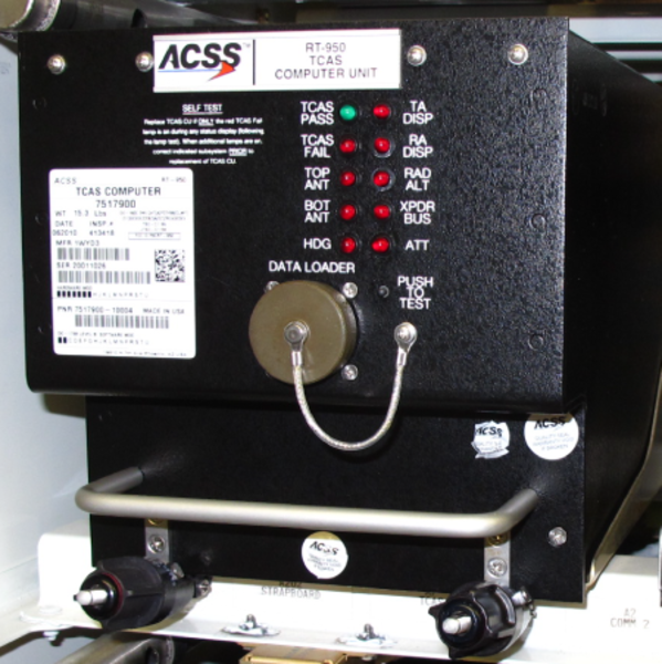
PUSH-TO-TEST button and PASS/FAIL indicator lamps are located on the CU front panel. Maintenance personnel can activate a self-test cycle and monitor fault data for the current and preceding flight legs using the indicator lamps.


05/04/16
Directional Antenna
The directional antenna is a disk-type, vertically-polarized antenna system. It contains a set of four antenna elements that transmit the interrogations at 1,030 MHz in one of four directions (0, 90, 180, or 270 degrees). The directional antenna, mounted on top of the aircraft fuselage, interrogates, receives replies and determines the bearing of the intruder. Since TCAS II is a vertical-only system, intruder bearing is not used in the computation of the escape maneuver. Intruder bearing is used only for display purposes and to enable the flight crew to locate the intruder visually.
The directional antenna is connected to CU by four coaxial cables. The antenna is capable of transmitting in four directions and receiving replies from all directions simultaneously for bearing information. The directional antenna has a maximum weight of 2.8 lbs (1.3 kg).

05/04/16
Bottom Omnidirectional Antenna
The omnidirectional antenna is a blade-type, vertically-polarized antenna. It has a frequency range of 960 to 1,220 MHz and a maximum weight of 0.25 lbs (0.114 kg). It has an N-type connector that connects to the receiver/transmitter.
The omnidirectional antenna, mounted on the bottom of the aircraft fuselage, does not provide directional information. It does, however, enable the CU to interrogate and receive replies from intruder aircraft located below that may be masked by the airframe.
This antenna is identical to the air traffic control (ATC) top and bottom antennas.

05/04/16
System Operation
TCAS interrogates mode C/S transponders on aircraft in the vicinity and listens for replies. By computer analysis of these replies, the CU determines which aircraft represent potential collision threats and provides appropriate display indications and advisories to the flight crew to ensure vertical separation.
Vertical separation is based on predictions from own aircraft altitude data and intruder altitude data supplied to the CU. The commanded maneuver ensures adequate vertical separation while causing the least deviation of the aircraft from its current vertical rate.
If the threat aircraft is itself equipped with TCAS II system, a coordination procedure via the air-to-air mode S data link is performed before displaying the advisory to the flight crew. This procedure assures that the advisories in each aircraft are compatible.
TCAS is designed to act as a backup to the air traffic control (ATC) system and the “See and Avoid” concept. TCAS has a surveillance volume defined by a horizontal radius of 14 nautical miles and a vertical range of ±8,700 feet of its own aircraft position with mode S equipped aircraft. TCAS continually interrogates transponders in that airspace, processes their replies, and tracks their flight paths.
Flight paths that are predicted to penetrate a collision area surrounding the aircraft are time based and vary as a function of horizontal and vertical closure speeds and distances between the TCAS aircraft and the intruder aircraft.
The TCAS communicates with its onboard systems to obtain:
- Coordination data from the transponders
- Altitude information from the radio altimeters
- ADC altitude for climb rate inhibit
The CU interfaces with the mute in/out discrete circuit for the aural warning prioritization. The TCAS mutes the IACs (other than stall) when its aural annunciation is active.
The TCAS 2000 communicates directly via ARINC 429 with the ATCs the IACs and the Rad Alts.
The TCAS transmits analog synthesized voice data to the audio panels and discrete data to the DAU 4 for the FDR.
The ADCs transmit a discrete which the TCAS uses to inhibit an increase climb command to the flight crew.
Change 7.0
In 1995 the European civil aviation conference (ECAC) states members agreed on mandatory implementation of airborne collision avoidance system II (ACAS II, which is the European acronym for TCAS II with Change 7.0). Change 7.0 incorporates improvements defined by the United States Federal Aviation Administration (FAA) from observations of TCAS systems to provide an international standard for collision avoidance logic, surveillance logic and aural messages.


Traffic Identification
Resolution Advisory (RA)
TCAS monitors a time-based warning area that extends 15-35 seconds from the time the intruder is predicted to enter the TCAS aircraft’s collision area. When an intruder enters this area, an escape strategy in the form of an RA is issued by TCAS CU.
RAs are only available for aircraft that transmit altitude data through Mode-C or Mode-S transponders. RAs are not available for aircraft with Mode-A transponders. As a special function, aircraft with TCAS 2000 or TCAS II systems can transmit opposite RAs to each other. The RA is a vertical maneuver recommended to the pilot by TCAS to increase or maintain vertical separation relative to an intruding aircraft. The RA is annunciated both visually and aurally. It consists of either a corrective advisory, calling for a change in aircraft vertical speed, or a preventive advisory restricting vertical speed change. The intruder amber circle TA symbol on the MFD changes to a red square RA symbol.
Traffic Advisory (TA)
TCAS monitors a time-based caution area that extends 20-48 seconds from the time the intruder is predicted to enter the TCAS aircraft’s collision area. When an intruder enters this caution area, traffic information in the form of a TA is issued by TCAS. The flight crew use this information as an aid to visually locate the intruder to avoid a conflict. TAs are available for all aircraft with Mode-A, Mode-C, or Mode-S transponders.
The intruder is represented as an amber circle TA symbol on the MFD. The traffic displayed includes the range, bearing and altitude (if available) of the intruder relative to the TCAS aircraft.
Proximate Traffic (PT)
Aircraft within 6.5 nautical miles and ±1,200 feet vertically are represented as a solid cyan diamond. Proximate traffic is shown to improve situational awareness in the event of a potential conflict with higher priority RA or TA aircraft. This warning is available independently or with RAs and TAs.
Other Traffic (OT)
Any transponder-replying traffic that is not classified as an intruder or proximate traffic, is within the display range and is within ±2,700 feet vertically for normal operation, is represented as a hollow cyan diamond (only in view when no RA or TA is in progress). The predicted flight paths of proximate traffic (PT) and other traffic (OT) do not penetrate the collision avoidance area of the aircraft.

The TCAS transmits its aural warnings as a synthesized voice through the audio integrating system. Each warning has the properties that follow:
| WARNING TYPE |
WARNING LEVEL |
DISPLAY SYMBOL |
AURAL WARNING (EXAMPLE) |
|---|---|---|---|
| Resolution Advisory (RA) | Highest | Filled red square | "CLIMB - CLIMB - CLIMB" "DESCEND - DESCEND - DESCEND" |
| Traffic Advisory (TA) | High | Filled amber circle | "TRAFFIC - TRAFFIC" |
| Proximity Traffic | Low | Filled cyan diamond | (Not applicable) |
| Other Traffic | Lowest | Empty cyan diamond | (Not applicable) |
Each warning symbol has a data label (of the same color) that shows the location and vertical movement of a monitored aircraft. The label has a number, a (+) or (−) sign, and possibly an (↑) or (↓) arrow. The label shows the data that follows:
- The number (when multiplied by 100 ft) gives the related altitude difference of the monitored aircraft
- The (+) or (−) sign shows if the monitored aircraft is above (+) or below (−) your aircraft
- The (↑) or (↓) arrow shows if the monitored aircraft increases (↑) or decreases (↓) its altitude (if more than 500 ft/min)
05/04/16
Control and Indication
TCAS Operations on RMU
The TCAS has three modes of operation (controlled from the radio management unit (RMU)):
- TA/RA Mode: This is the usual mode that gives the most protection from all aircraft in the TCAS area. During this mode, the TCAS supplies the usual RAs, TAs, and other indications
- TA Mode: During this mode, the TCAS monitors all aircraft that are farther than the TA area (proximity traffic). The TCAS gives the usual TAs but prevents RAs for adjacent aircraft that have sufficient separation (e.g., during parallel landings and take-offs). Also, the TCAS sets this mode automatically when the altitude of the aircraft is less than 500 ft above ground level (AGL)
- Test Mode: This is the self-test mode that does a check of most TCAS functions, displays, and interfaces. When you make the applicable menu selection on the RMU, the test mode starts and you hear “TCAS TEST”. During the test, the RMU shows TEST, the MFD shows a TCAS test pattern, and the PFD shows the pitch symbols. After 8 seconds, the self-test stops. Then, the MFD and PFD show the test results and you hear “TCAS TEST PASS” or “TCAS TEST FAIL”
TCAS Window Annunciators
Mode Line Select Key
Press this key to move the cursor to this line. Press this key again or turn either tuning knob to select TCAS/ATC operation modes.
- TA only will not display resolution advisory on the PFD.
- TA/RA full operation of TCAS is selected
Surveillance Window Line Select Key
Press this key to move the cursor to this line. Press this key again or turn either tuning knob to select one of the following surveillance window sizes:
- NORMAL: Selects traffic advisories (TA) ±1,200 feet when the system is in AUTO, and ±2,700 feet when system is in MANUAL
- ABOVE: Indicates that the system displays TAs +7,000 feet above to −2,700 feet below the aircraft
- BELOW: Indicates that the system displays TAs +2,700 feet above to −7,000 feet below the aircraft
These selections are determined by the flight crew, depending on the vertical path of the aircraft. NORMAL would be selected during level flight. ABOVE or BELOW would be selected during high rate climbs or descents.
RMU 1 and RMU 2 can select these functions, but both MFDs display the same annunciation on TCAS display. If either RMU is in the cross-side control mode (with magenta banner lines) that RMU will control the cross-side display.
In addition, the digit in the banner line (TCAS DSPY 1 or 2) indicates which side MFD will be affected by the above-described key press selections.
Range
The range of the TCAS zoom window can be set to 6, 12, 20, 40 nm (80 and 120 nm selectable) by toggling the line select key adjacent to the range annunciation, or by rotating either of the tune knobs when the cursor is around the range selection.
The 80 nm and 120 nm TCAS RANGE 80/120 - Enable is selectable on the RMU setup page. The 120 nm range is selectable but is not available on the Global.


ATC/TCAS RMU Control Page
ATC/TCAS Line Select Key
Pressing the ATC/TCAS line select key on the system page menu will display the ATC/TCAS control page with the following:
Intruder Altitude
Using the adjacent line select key, the intruder altitude can be toggled between:
- REL – the target’s altitude is displayed relative to one’s own aircraft (i.e. −1,200/ + 500)
- FL – the target altitude is displayed as a flight level (i.e. FL200)
Note:
If the flight level is selected, the TCAS display returns to REL after 15 seconds.
TA Display
Using the adjacent line select key, the intruder TA display can be toggled between:
- AUTO – the traffic targets are displayed only when a TA or RA target condition exists
- MANUAL – all traffic targets are displayed in the viewing airspace
ATC Altitude
This line indicates that the transponder selected on the main tuning page is communicating at a displayed altitude. This is not a control feature, only a cross check. Uncorrected altitude is always displayed. It represents the active transponder information only. The air data source is annunciated by ATC ALTITUDE 1 or ATC ALTITUDE 2. The uncorrected altitude is in units of feet.
Return to Radios
To return to the main radio tuning page, press the line select key, adjacent to the "Return to Radios".
RMU Setup Page
MAINTENANCE Line Select Key
Pressing the MAINTENANCE line select key and then the RMU SETUP line select key will display the RMU SETUP page. On the setup page, TCAS display and range selection are provided.
TCAS Display
Pressing the adjacent line select key of TCAS display will either enable or disable the TCAS display on the RMU.
TCAS Range 80/120
Pressing the adjacent line select key of TCAS range 80/120 will either enable or disable the range selection of 80 and 120 nm.


TCAS Display
TCAS information is displayed on both PFDs and MFDs.
PFD Mode
PFD displays TCAS operating modes, failure annunciations, and RAs.
There are two types of RAs, corrective and preventive. A corrective RA instructs the flight crew to deviate from the current vertical rate to avoid the intruder. A preventive RA instructs the flight crew to avoid certain deviations from the current vertical rate.
RA commands from the CU are in the form of aural vertical speed commands. The vertical maneuver information is displayed on the attitude sphere.
PFD TCAS Mode Annunciations
| Annunciations | Color | Condition |
|---|---|---|
| "TCAS FAIL" | Amber | TCAS CU has detected a fault |
| "TCAS TEST" | Red | TCAS TEST is active |
| "TCAS OFF" | White | TCAS is not active - Standby mode |
| "TA ONLY" | White | TA only mode is active |
| "RA FAIL" | Amber | RA mode failed |
PFD Vertical Maneuver TCAS Symbology
The RA on the ADI consists of a green rectangle and two sets of red goal posts. The green rectangle is to advise pilot of a fly-to-zone. The two red goal posts forming an avoidance zone advise the pilot of a fly-out area.
The flight director command bars are removed when an avoidance zone is displayed. The aircraft symbol is red when aircraft nose is below the pitchup target or above the pitch-down target. The aircraft symbol is green when aircraft enters into the fly-to-zone.

MFD Display
TCAS displays use color-coded symbols and data tags to map traffic aircraft on the MFD. TCAS can be displayed as a zoom window on the MFD map and plan mode displays, or as an overlay on the map display.
The MFD controller controls TCAS range on the map display and the RMU controls TCAS range on the zoom window.
TAs are annunciated aurally and are shown on the multifunction displays (MFDs). The flight crew uses this information only as an aid to visuallylocate the intruder in order to avoid a conflict.
MFD display gives pictorial information about the bearing and distance of other Mode C and Mode S transponder-equipped aircraft in the area. The traffic display also shows the relative altitude and vertical direction of the other aircraft.
If TCAS cannot calculate bearing from another aircraft due to directional antenna shadowing or failure, that aircraft is not displayed on the MFD map display. A NO BEARING annunciation is displayed and information regarding the aircraft’s distance, relative altitude and vertical direction are provided in digital format, below the map display, if the intruder becomes a threat (TA or RA level).
TCAS display ranges are 6, 12, 20, and 40 nm, selectable from the RMU. The TCAS traffic symbols will only be displayed when TCAS is selected on the onside MFD controller.
Traffic Symbols
Four traffic symbols are used based on threat levels: solid circle, solid square, solid diamond, and hollow diamond. A different color is assigned to each symbol type.
| GRAPHIC SYMBOL | COLOR | DISPLAY FUNCTION |
|---|---|---|
| Solid Square | Red | Resolution Advisory (RA) |
| Solid Circle | Amber | Traffic Advisory (TA) |
| Solid Diamond | Cyan | Proximate Traffic (PT) |
| Hollow Diamond | Cyan | Other Traffic (OT) |
Data Tags
Two styles of data tags may be displayed on the MFD. The style displayed is determined by the RMU selection of ALT:REL or ALT:FL.
When ALT:REL is selected, a data tag, made up of a two-digit number and a plus (+) or a minus (−) sign, appears either above or below the intruder aircraft symbol and represents the relative altitude of the intruder, in hundreds of feet, as referenced to the TCAS-equipped aircraft.
+ intruder is above the TCAS-equipped aircraft
− intruder is below the TCAS-equipped aircraft
The data tag may also include a vertical arrow. If the arrow is pointing up, the intruder aircraft is climbing at a rate greater than 500 feet per minute (FPM). If the arrow is pointing down, the intruder is descending at a rate greater than 500 fpm. When ALT:FL is selected, the data tag consists of a three-digit number, which represents the intruder’s uncorrected altitude in hundreds of feet above mean sea level (ASL).
Off Scale Traffic Symbol
RA and TA targets that are being tracked but not within the display range are shown as half symbols at the edge of the TCAS writing area and at the correct bearing. A data tag is attached to each symbol. PT and OT Symbols will not be displayed when out of range.
TCAS Altitude Band Annunciator
ABOVE or BELOW is annunciated in cyan, when relative altitude is selected from the RMU to look well above or well below the normal TCAS altitude band.
TCAS Zoom Window
The TCAS mode annunciations and traffic information in the zoom window (except for the range) is identical to the display on the Map mode.


TCAS/MFD Controls
TCAS display on the MFD is controlled from the MFD Controller. By pushing the TCAS pushbutton (OFF → TCAS [zoom window] → TCAS MAP → TCAS [zoom window] → OFF), the TAs can be displayed on the MFD in one of two ways:
- TCAS zoom window display is shown on the MFD
- Traffic symbols are added to the existing map navigation display with or without WX
TCAS modes are displayed when TCAS is selected for display. When TCAS is selected on the MFD, a ring of 12 small circles is displayed around the own aircraft symbol. The ring has a radius of two nautical miles, and the dots represent the clock hour positions.
Range is controlled through the up/down arrows on the MFD controller. The 2 mile range ring is removed when the range is greater than 20 NM and the TAs are removed when the range is 50 NM or greater.
Note:
TCAS data can be displayed in only one format or the other at one time, but not both. When MFD plan mode is selected, TCAS data can only be displayed in the MFD zoom window area.
MFD TCAS Mode Annunciations
| ANNUNCIATIONS | COLOR | CONDITION |
|---|---|---|
| "TCAS FAIL" | Amber | TCAS CU has detected a fault |
| "TCAS TEST" | Red | TCAS functional TEST is active |
| "TCAS OFF" | White | TCAS is not active -Standby mode |
| "TA ONLY" | White | TA only mode is active |
| "TCAS RNG" (Pre IAC Batch 2 only) | White | TCAS zoom enable indicates disable and the Map range exceeds 50 NM |
| "TCAS" | White | TCAS is selected to display and none of the above TCAS annunciations is currently displayed |
TCAS Traffic Display
When MFD is in map mode, the TCAS traffic information is displayed as long as neither the ”TCAS OFF“ nor the ”TCAS FAIL“ message is displayed.

TCAS II Aural Messages
TCAS II generates aural alerts or messages that are announced over the aircraft’s audio system. These messages accompany the visual RA or TA display.
TCAS audio level can not be controlled by the flight crew. TCAS aural alert is inhibited when STALL or EGPWS audio is activated.
If a logic change occurs before the message is complete and a new alert is initiated, the original alert is terminated and the new alert announced immediately. Messages are softened or strengthened depending on the urgency of the situation.
| RESOLUTION ADVISORY (RA) / TRAFFIC ADVISORY (TA) | AURAL ALERT |
|---|---|
| Traffic alert | TRAFFIC - TRAFFIC |
| Initial preventive RA | MONITOR VERTICAL SPEED |
| Non-crossing, maintain rate RAs (corrective) | Maintain vertical speed, maintain |
| Altitude crossing, maintain rate RAs (corrective) | Maintain vertical speed, crossing maintain |
| Weakening of corrective RAs | Adjust vertical speed, adjust |
| Corrective climb | CLIMB - CLIMB |
| Corrective descend | DESCEND - DESCEND |
| Altitude crossing climb (corrective) | CLIMB, CROSSING CLIMB - CLIMB, CROSSING CLIMB |
| Altitude crossing descend (corrective) | DESCEND, CROSSING DESCEND - DESCEND, CROSSING DESCEND |
| Corrective reduce climb | Adjust vertical speed, Adjust |
| Corrective reduce descend | Adjust vertical speed, Adjust |
| Reversal to a climb (corrective) | CLIMB, CLIMB NOW - CLIMB, CLIMB NOW |
| Reversal to a descend (corrective) | DESCEND, DESCEND NOW - DESCEND, DESCEND NOW |
| Increase climb (corrective) | INCREASE CLIMB - INCREASE CLIMB |
| Increase descent (corrective) | INCREASE DESCENT - INCREASE DESCENT |
| Clear of conflict | CLEAR OF CONFLICT |
Aural Warning Prioritization
The aural warning prioritization between the IAC, EGPWS, and TCAS is required so that multiple aural annunciations do not go out at the same time. This could result in aural annunciations which are not discernible. With this prioritization, the flight crew will only hear one voice at any one time. The prioritization between the systems are as follows:
- "STALL"
- EGPWS aural annunciations
- TCAS aural annunciations
- IAC aural annunciations
The IAC inhibits the EGPWS and TCAS aural annunciations when "STALL" is sounding. The EGPWS mutes the TCAS and IACs (other than STALL) when its aural annunciations are active.
The TCAS mutes the IACs (other than STALL) when its aural annunciations are active.
Traffic Advisory Aural Alert
The traffic advisory aural alert is the message TRAFFIC – TRAFFIC spoken once. This alert occurs when TCAS predicts an intruder will enter the collision area within 35 to 45 seconds. Simultaneously, the TCAS traffic display displays the location of the intruder.
Resolution Advisory Aural Alerts
Resolution advisories indicate evasive vertical maneuvers calculated to:
- Increase separation between the TCAS aircraft and the intruder (corrective advisory) or to
- Indicate that certain changes in vertical speed are not recommended (preventive advisory)
RA messages made up of a single word are repeated three times; longer messages are repeated twice.
A CLEAR OF CONFLICT announcement confirms that the encounter has ended and separation is increasing as follows:
- PFD RED goal posts and GREEN rectangle are removed
- Intruder no longer appears as a RED square

System Interface
Several additional components interface with the TCAS. Their functions are:
- Aural warnings are sent through the audio control units
- Traffic advisories (TAs) are sent to the IACs to be displayed on the MFDs
- Resolution advisories (RAs) are sent to IACs to be displayed on PFD
- Altitude data originates in the MADCs
- TCAS mode, range, and vertical mode control is from the RMU
- Command data from the RMU passes through the transponder to TCAS CU
Signal Interface
High-Speed ARINC 429 Outputs
- Two sets of high-speed ARINC 429 buses for communication with two mode S transponders
- TA/RA display 1 and 2 buses are connected to the IACs. They convey both traffic information and resolution advisory information for display on MFDs and PFDs
Low Speed ARINC 429 Input
- Altitude information from radio altimeter
Discrete Inputs
- MADCs altitude >15,000 feet for climb rate inhibit (>2,500 fpm)
- WOW for inhibit test in flight
- Mute in discrete to shut down TCAS audio
Discrete Output
- Advisory discretes to DAU 4 to translate into ARINC 717 format to flight data recorder for recording information during a resolution advisory event
- Mute out discrete to shut down IAC generated audios except STALL
- Analog input and outputs
- 28 VDC suppression signal is connected between TCAS, ATC1, ATC2, DME1, and DME2
- Synthesized voice is output to audio panels
Power Inputs
TCAS computer unit operates on SPDA 4 28-VDC essential bus.

System Monitoring
Power-On Built-In Test
During power-on built-in test (PBIT), the CU tests all circuits to ensure correct operation and control.
Continuous Built-In Test
During operation, the CU monitors the circuits for correct operation (CBIT). If during PBIT or CBIT the CU detects system faults, it reports them on its front panel LED display. Its memory stores system status and fault information for 10 consecutive flight legs. A flight leg is the interval between the weight-off-wheels and weight-on-wheels condition during which TCAS is operative.
By recalling the stored data, maintenance personnel can evaluate in-flight performance on the ground and isolate a current or previous failure to a specific LRU or LRU interface. Repressing the PUSH TO TEST button within 10 seconds (after a normal self-test) will access the CU’s memory. It will then display its memory from the last 10 flights.
TCAS is programmed to perform automatic self-test at power-up and continuous self-test during operation. See table below.
| TEST SEQUENCE | ACTIVATION | TEST INDICATION |
|---|---|---|
| Power-on self-test | Self-test is activated with each application of system power | No indication unless a fault is detected. System status/fault data is stored in memory for 10 consecutive flight legs. Data can be recalled by doing the commanded self-test on the ground |
| Continuous self-test | Executed automatically as part of normal TCAS in-flight operation | No indication unless a fault is detected. System status/fault data is stored in memory for 10 consecutive flight legs. Data can be recalled by doing the commanded self-test on the ground |
| Commanded self-test | Push CU front panel push to test button, or RMU TST button |
|
| Push the push to test button again before the previous 10-second display period has elapsed |
|
|
| Push the push-to-test button before the end of each succeeding display period |
|
|
|
** Note: As EDS does not support displaying the status/fault data, TCAS front panel lamps are used to display the status/fault data. |
||
System Test
Initiated Built-In Test – RMU/TCAS CU
PAST can be activated at any time on the ground in either active or standby modes, but is inhibited in flight. PAST can be activated either from the RMU radio page or the TCAS CU front panel.
On the RMU radio page:
- Press a line select key to place cursor in the bottom left window
- Press the TST key
On the TCAS CU front panel, press the self-test button.
The following should be observed:
- Aural annunciation TCAS TEST is heard
- Test pattern displayed on the MFD
- RA at 3 o’clock 2 nm 200 feet above level flight
- ATA at 9 o’clock 2 nm 300 feet below climbing
- PT at 1 o’clock 3.6 nm 1,100 feet below descending
- OT at 11 o’clock 4 nm 2,000 feet above level flight
- Test pattern displayed on the PFD
- Up advisory "TCAS pitch target"
- Fly to zone "TCAS pitch target"
- Down advisory "TCAS pitch target"
- After 8 seconds, aural annunciation TCAS TEST PASS is heard, and the test pattern is replaced by normal display
- If self-test fails, TCAS TEST FAIL is heard and TCAS FAIL appears on the PFD below the VSI display
PAST Failure Indications
If the test fails, monitor the TCAS CU front panel LEDs for the failure indication. Table details possible failure conditions and possible corrective actions.
TCAS Fault Indications and Corrective Actions
| LED LABELS | FAILURE INDICATIONS | POSSIBLE CORRECTIVE ACTIONS |
|---|---|---|
| TCAS PASS | TCAS was operational in the flight displayed. | N/A |
| TCAS FAIL | TCAS failed in the flight displayed. | Remove and replace TCAS CU, if there is no other indication. |
| TOP ANT | Top antenna or cabling connectors to top antenna are failed or miswired. | Verify antenna cabling and connections by verifying resistance at TCAS CU tray. Repair cabling or replace antenna, as required. |
| BOT ANT | Bottom antenna or cabling connectors to top antenna are failed or miswired. | Verify antenna cabling and connections by verifying resistance at TCAS CU tray. Repair cabling or replace antenna, as required. |
| HDG | Heading input function is not used. | N/A |
| RA LOG | Function is not used. | N/A |
| TA DISP | The LRU providing the traffic advisory display function (on one or both sides) is not available to TCAS. | Verify wiring and power to TA MFD display (on both sides of the cockpit). Check that TA valid discretes 1 and 2 are 10 ohms to ground maximum. Repair wiring or replace MFD, as required. |
| RA DISP | The LRU providing the resolution advisory display function (PFD) is not responding to TCAS inputs. | Verify wiring and power to RA PFD display (on both sides of the cockpit). Check that RA valid discretes 1 and 2 are 10 ohms to ground maximum. Repair wiring or replace PFD, as required. |
| RAD ALT | One or both of the radio altimeter inputs to TCAS has failed. | Verify wiring and power to radio altimeter. Check that RAD valid discretes 1 and 2 are 28 VDC or ARINC 429 is valid. Repair wiring or replace radio altimeter, as required. |
| XPDR BUS | Both of the transponder interfaces to TCAS have failed. | Verify wiring and power to transponder. Check for data on TX 429 buses 1 and 2. Repair wiring, or replace transponder(s), as required. |
| ATT | Attitude input function is not used. | N/A |
Technical Characteristics
| GENERAL | |
|---|---|
| Power Requirements | 28 VDC/80 W |
| Frequencies T/X R/X | 1,030 MHz1,090 MHz |
| Transmit Power | 335 Watts nominal |
| Computer Unit O/P | Discretes Digital ARINC 429Analog audio |
| Mutual Suppression | 28 VDC nominal on suppression line to other L-band systems |

