


05/18/16
Overview
The bleed air leak detection system protects the aircraft against hot air leaks from the air ducts of the bleed air system, the anti-icing system and the air conditioning trim air system. This system protects the components and the structure near the ducts against an overheat condition and the risk of fire.
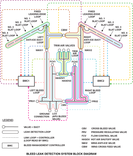
The bleed air leak detection system consists of dual bleed leak detection sensing elements (loops) and two bleed management controllers (BMC).
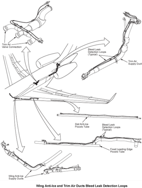
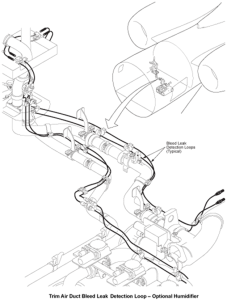
The bleed air system has sense elements (loops) installed along the insulated ducts of the pneumatic system to sense any overheat caused by leaks. The wing anti-ice system has loops installed along the wing supply ducts and piccolo tubes. The air conditioning system has loops installed along trim air duct. The duct insulation has holes to direct any leaks over the sense elements.
The bleed management controllers (BMCs) continuously monitor the loops to determine if a leak has occurred. If a leak is detected, the bleed management controllers (BMCs) or the air conditioning system controllers (ACSCs) will automatically set the valves to isolate the defective area and stop the leak.
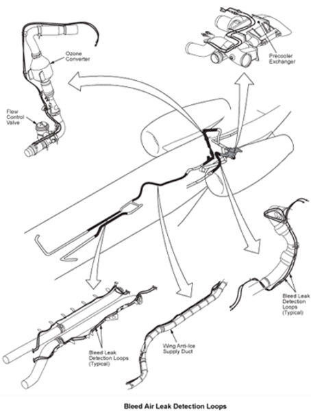
Bleed Leak Detection Loops
The bleed leak detection loops consist of two concentric tubes, the space between them being filled with an insulated eutectic salt. In case of a local temperature increase, the salt becomes conductive and the measured resistance between the tubes drops suddenly.
The bleed air leak detection system has the detection loops that follow:
- Left bleed leak detection loop
- Right bleed leak detection loop
- Trim air bleed leak detection loop
- Wing supply leak detection loop
- Fixed leading edge wing leak detection loop
- Slat 1 wing leak detection loop
- Slat 2 wing leak detection loop
- Slat 3 wing leak detection loop
- Slat 4 wing leak detection loop
All bleed air ducts are monitored through an arrangement of dual loops. The wings, however, are monitored by a single loop for each of the outboard and inboard sections, and by another single loop that covers both sections of the wing.


05/18/16
System Operation
The monitoring channel (channel B) of the bleed management controller (BMC) continuously monitors (CBIT) the resistance of the bleed air leak detection elements. When both loops in the same circuit indicate a bleed air leak has occurred, the controller will isolate the affected manifold by closing the appropriate valves.
When a leak is detected (by air leaking from holes in insulation shell onto the leak detection loops), the appropriate BLEED LEAK, WING A/I LEAK, or TRIM LEAK caution message is displayed on EICAS and the BMC and/or the ACSC automatically close the relevant valves.
Left Bleed Leak Detection Loop
The left bleed leak detection loop is attached to the frame adjacent to the left supply duct assembly. It is installed in the aft equipment compartment and the left pylon area.
At 255°F (123°C) and above, the loop senses a leak. When a leak is sensed, the EICAS primary page shows a L BLEED LEAK indication. At the same time, the bleed management controller or the air conditioning system controller automatically closes the applicable shut-off valves.

Right Bleed Leak Detection Loop
The right bleed leak detection loop is attached to the frame adjacent to the right supply duct assembly. It is installed in the aft equipment compartment and the right pylon area.
At 255°F (123°C) and above, the loop senses a leak. When a leak is sensed the EICAS primary page shows a R BLEED LEAK message. At the same time the bleed management controller or the air conditioning system controller automatically closes the applicable shut-off valves.

Trim Air Bleed Leak Detection Loop
The trim air bleed leak detection loop is attached to the frame adjacent to the trim air duct assembly. It is installed in the aft power distribution/ECS compartment. At 255°F (123°C) and above, the loop senses a leak. When a leak is sensed, the EICAS primary page shows a TRIM LEAK message. At the same time the bleed management controller or the air conditioning system controller automatically closes the applicable shut-off valves.


Wing Supply Leak Detection Loop
There are two wing supply leak detection loops, one on each side of the fuselage. Each leak detection loop is attached to the frame adjacent to its related wing supply duct assembly. The loops are installed in the mid-lower fuselage compartment.
At 255°F (123°C) and above, the loops sense a leak. When a leak is sensed, the EICAS primary page shows a WING A/I LEAK message. At the same time the bleed management controller or the air conditioning system controller automatically closes the applicable shut-off valves.

Fixed Leading Edge Wing Leak Detection Loop
There are two fixed leading edge wing leak detection loops, one in each fixed leading edge. Each loop is attached to the frame adjacent to its related wing supply duct assembly.
At 460°F (238°C) and above, the loops sense a leak. When a leak is sensed, the EICAS primary page shows a WING A/I LEAK message. At the same time the bleed management controller or the air conditioning system controller automatically closes the applicable shut-off valves.

No. 1 Slat Wing Leak Detection Loop
There are two No. 1 slat wing leak detection loops, one in each No. 1 slat. Each loop is attached to the frame adjacent to its related piccolo tubes.
At 460°F (238°C) and above, the loop senses a leak. When a leak is sensed, the EICAS primary page shows a WING A/I LEAK message. At the same time the bleed management controller or the air conditioning system controller automatically closes the applicable shut-off valves.

No. 2 Slat Wing Leak Detection Loop
There are two No. 2 slat wing leak detection loops, one in each No. 2 slat. Each loop is attached to the frame adjacent to its related piccolo tubes.
At 460°F (238°C) and above, the loop senses a leak. When a leak is sensed, the EICAS primary page shows a WING A/I LEAK message. At the same time the bleed management controller or the air conditioning system controller automatically closes the applicable shut-off valves.
No. 3 Slat Wing Leak Detection Loop
There are two No. 3 slat wing leak detection loops, one in each slat 3. Each loop is attached to the frame adjacent to its related piccolo tubes.
At 238°C (460°F) and above, the loop senses a leak. When a leak is sensed, the EICAS primary page shows a WING A/I LEAK message. At the same time the bleed management controller or the air conditioning system controller automatically closes the applicable shut-off valves.
No. 4 Slat Wing Leak Detection Loop
There are two No. 4 slat wing leak detection loops, one in each slat 4. Each loop is attached to the frame adjacent to its related piccolo tubes.
At 238°C (460°F) and above, the loop senses a leak. When a leak is sensed, the EICAS primary page shows a WING A/I LEAK message. At the same time the bleed management controller or the air conditioning system controller automatically closes the applicable shut-off valves.


For all bleed air leaks, the relevant valves are automatically closed by the BMC and/or the ACSC.
| LEAK LOCATION | DETECTED BY | INDICATION | BMC ACTION |
|---|---|---|---|
| Overboard wing | Loop 1 and opposite loop 8 | WING A/ICE LEAK caution msg | Automatic closure of both wing anti-ice valves (WAIVs) and the wing cross-bleed wing (CBW) |
| Inboard wing | Loop 2 and opposite loop 8 | WING A/ICE LEAK caution msg | Automatic closure of both WAIV and the CBW |
| Left wing anti-ice supply duct | Loop 3 (both) | WING A/ICE LEAK caution msg | Automatic closure of both WAIV and the CBW |
| Right wing anti-ice supply duct | Loop 4 (both) | WING A/ICE LEAK caution msg | Automatic closure of both WAIV and the CBW |
| Trim air supply duct | Loop 5 (both) | TRIM AIR LEAK caution msg | Automatic closure of both hot air shutoff valves (HASOVs) |
| Left bleed air duct | Loop 6 (both) | L BLEED LEAK caution msg | Automatic closure of left pressure regulating valve (PRV), APU load control valve (LCV) and cross-bleed valve (CBV) |
| Right bleed air duct | Loop 7 (both) | R BLEED LEAK caution msg | Automatic closure of right PRV and CBV |
System Monitoring
Power On Built In Test (PBIT)
Power On Built In Tests (PBIT) are performed automatically on power-up except in the following circumstances:

The Bleed Leak Detection Loops are tested (internal test and external interface test) during PBIT by the monitoring channel.
If there is a failure of a single loop or both loops of the same circuit, the appropriate CAS FAULT or FAIL message will be displayed and a CAIMS report will be generated.
Note:
During PBIT, the internal conductor of the loops is tested for continuity. If continuity is not achieved due to a mechanical break in the conductor, the loop is declared failed. However, if a break does occur, the loop remains functional unless a second break occurs:
- When both loops are operative during power-up test, an AND logic is used (leak detection on both loops triggers the signal) to avoid false warnings
- When one of the loops is inoperative during power-up test, an OR logic is used (leak detection on the operative loop to trigger the signal) to increase dispatch reliability
Continuous Built-in test
During continuous built-in test (CBIT) the bleed leak detection loops are tested. During operation, if a single loop only detects a leak (fault), after a period of time, that loop will be declared failed and a fault CAS message will be displayed.
A short circuit will be detected during the CBIT only and will have the associated CAS message posted. For more information on continuous BITE of the BMC, see "Bleed Air Supply System".
Bleed/Anti-Ice Synoptic Display
Bleed air leaks are displayed on the bleed/anti-ice synoptic page and air conditioning synoptic page by changing of the color of the duct fill. The appropriate automatic valve closures can also be viewed during a leak event.

System Test
The Bleed Management Controllers can be tested via CAIMS.
During IBIT the Bleed Leak Detection Loops are tested. If the system passes the test a "Test Results: Pass" message will be displayed (on the PMAT).
If a failure occurs, the appropriate CAIMS report will be generated, and for certain failure conditions, a CAS message will also be generated. The CAIMS report will identify the failed unit.

09/24/20
Component Location Index
| Component Location Index | |||
|---|---|---|---|
| IDENT | DESCRIPTION | LOCATION | IPC REF |
| - | BLEED LEAK-DETECTION-LOOPS | ZONE(S) 161/162 ZONE(S) 171/172 ZONE(S) 311/410 ZONE(S) 312/420 ZONE(S) 510/610 ZONE(S) 511/611 ZONE(S) 512/612 ZONE(S) 513/613 ZONE(S) 514/614 |
36-12-01 [ GX ] [ GXRS ] [ G5000 ] 36-12-02 [ GX ] [ GXRS ] [ G5000 ] 36-12-03 [ GX ] [ GXRS ] [ G5000 ] 36-12-04 [ GX ] [ GXRS ] [ G5000 ] 36-12-05 [ GX ] [ GXRS ] [ G5000 ] |