


Overview
The gray water system consists of drain lines and drain valves plumbed to the forward and aft drain masts on the lower fuselage of the aircraft. The drain masts and lines are heated to prevent freezing. The galley sink is equipped with an electronically controlled drain valve with an adjacent switch to open and close the drain.
The black water system is a vacuum waste system. An Evac toilet is located in each lavatory. This type of toilet utilizes vacuum (low pressure) provided by a vacuum generator assembly. The vacuum is created by a vacuum generator up to 16,000 feet. Above this altitude, the differential pressure between the cabin and ambient pressure is sufficient for waste tank operation.
The toilets use fresh water supplied by the potable water system for the flushing liquid.
The waste is collected in the waste tank in the aft right fairing area. Each toilet is interfaced to the cabin electronics system to receive the flush activation signal and to indicate toilet system faults. The FLUSH switch has a two-second time delay before activating, and a 15 second reset time delay. The FLUSH switch back lighting will be green when the toilet is ready, amber during a flush, and red when there is a SYSTEM INOP, TOILET JAM, or SERVICE MODE fault. An interlock switch on the external service panel prevents operation of the toilet vacuum generator while the external service panel is opened.


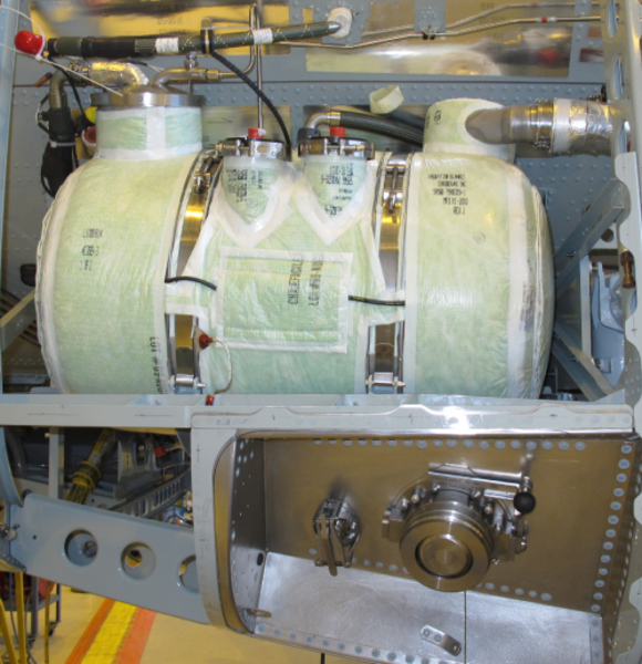
Waste Tank
The waste tank has a useable capacity of 16 U.S. gal (60.5 liters). It is made from lightweight stainless steel. An air/water separator vents fumes overboard an prevents water from freezing in the exhaust duct. Two ultrasonic full level sensors will shut down the waste system if both sensors signal a full tank condition.
A thermal blanket is attached to the lower half of the tank to prevent freezing of the contents of the tank. The rinse nozzle receives cleaning fluid from the rinse nipple to clean the waste tank during servicing. A differential pressure (Delta P) sensor continuously monitors tank fluid level by liquid column height. Quantity information is displayed on the galley TSE.

Aft and Forward Toilet Assembly
The toilet assembly consists of a flush control unit, a flush valve assembly, a rinse valve assembly, a rinse header with nozzle, a manual valve close handle, and the bowl. The toilet bowl is coated with Teflon. The flush control unit has an integral circuit breaker.
The flush valve is electrically operated by the flush control unit. If the flush valve does not close upon command, vacuum will be lost and the other toilet can not be used. The manual close handle can be used to close the flush valve to allow vacuum to build up.

CIRCUIT BREAKER

MANUAL CLOSE HANDLE

Heater Interface Unit (HIU)
The waste system uses electric heaters to prevent freezing in the tank, lines, and components.
The HIU monitors the vacuum waste system heaters, and reports a fault to the Logic Control Module (LCM), which then communicates the failure to the cabin electronics system. The HIU monitors for temperature sensor opens or shorts, open heating elements, or high currents.
The LCM combines the heater groups into two types:
- Tank Heaters (groups 2 - 5)
- Fairing plumbing heaters (groups 6 - 9)
A Lamp Test switch verifies lamp operation.

Logic Control Module (LCM)
The LCM provides system logic for both the forward and aft toilets. The primary function of the LCM is to provide system monitoring. The LCM monitors system performance to maximize system availability, while preventing system use if a substantial failure should occur.
The LCM receives inputs from the waste tank ultrasonic level sensors and controls the power to the toilet assemblies. The LCM continuously monitors the level sensors and if both indicate full for five seconds, it interprets this as a full waste tank.
The LCM will provide TANK FULL and ULTRASONIC SENSOR failure indications, and will disable the system (SYSTEM INOP) as required.

Waste External Service Panel
The waste system is serviced through an external service panel on the right aft wing fairing. The servicing decal is located on the service panel door.
When the service door is opened, the operation of the vacuum generator is inhibited to enable the tank contents to flow by gravity into the waste cart.


04/20/17
Vacuum Generator
The vacuum generator is a double-headed bellows pump, or blower, that produces the suction necessary to operate the waste system below 16,000 feet. The unit is powered with 200 VAC, 3-phase power from AC PDE 3.
The vacuum switch senses the pressure difference between the cabin and waste tank. The vacuum switch enables the vacuum generator as required to maintain adequate system vacuum. At higher altitudes the vacuum generator is disabled since the ambient pressure difference provides enough vacuum for operation.

System Operation
When cabin AC power is applied, the vacuum generator automatically begins operation to create a negative pressure in the waste tank. When the vacuum switch detects sufficient negative pressure, the vacuum generator stops.
The vacuum generator produces suction necessary to operate the waste system below 16,000 feet. At higher altitudes the vacuum generator is disabled since the ambient pressure difference provides enough vacuum for operation. Therefore, at high altitudes, the toilets will remain functional even if the vacuum generator is inoperative.
The galley sink drain is activated by pressing the SINK DRAIN switch located adjacent to the sink. The gray water drain valve allows water to drain without losing aircraft pressurization. The galley gray water, including ice drawer water, drains through the gray water drain valve. The motorized drain valve has a manual override feature that can be used if the drain fails.
When the FLUSH switch is selected, (see Flush Cycle illustration below) the flush control unit sends commands to the rinse valve and the flush valve.
The rinse valve opens to send a small amount of water (7 ounces, 207 ml) into the toilet bowl. The flush valve opens, allowing the vacuum to draw the toilet contents into the waste tank. After a few seconds, the flush valve closes, allowing the vacuum to build again for the next flush cycle.
Sensors detect proper operation of the system and disable the system if the waste holding tank is full, or if there is a significant system failure. In the event the toilet drain valve becomes jammed in the open position, a handle is provided to manually close the drain valve.
Opening the motorized valve manually overrides the safety feature provided by the system, and even though water can drain from the masts, this feature should only be used for dispatch purposes, and water system troubleshooting should occur as soon as possible.
CAUTION:
MANUALLY OVERRIDING A MOTORIZED VALVE DISABLES THE WATER SPILL PROTECTION. WHERE FAUCETS HAVE BEEN LEFT OPEN AND THEN THE SYSTEM IS POWERED UP AND RUNNING, OR IF THE WATER SYSTEM IS SERVICED, WATER SPILLAGE CAN OCCUR.


FLUSH CYCLE
System Test
Two push button test switches are located on the LCM. One switch performs an LCM Lamp Test. The other switch initiates a system functional test. During this test, the TANK FULL light illuminates for 10 seconds, then after 5 seconds the SYSTEM INOP light illuminates for 10 seconds.
