


05/19/16
Overview
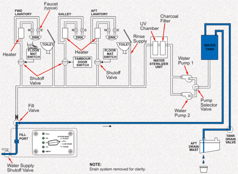
The potable water system (PWS) supplies potable water to the lavatory sinks, galley sink, and lavatory toilets. The potable water system drains gray water from the galley sink and lavatory sink to the outside of the aircraft. The potable water system (PWS) is a freeze protection system. The PWS is a pump-fed, constant pressure, recirculation system that stores and supplies water for the necessary services.
The potable water system uses dual water pumps, electronically controlled valves, and a network of plumbing to form a re-circulating loop. The Electronic Interface Box (EIB) is the main controller of the PWS and activates or deactivates the pumps, valves, drain masts, and heaters, depending on the PWS selected mode of operation. Five level sensors in the water tank provide water level indication to the Cabin Electronics System (CES). The PWS is interfaced to the CES for control and fault monitoring via the EIB. The PWS is also interfaced to the Waste Disposal system for draining purposes and for supply to the toilets.
The components of the potable water system are located throughout the cabin. On the Global XRS, the water tank is located on the left side of fuselage just forward of the baggage compartment door and attached to the fuselage structure with six mounting attachments. On the Global 5000, the water tank is located on the left side of the fuselage just forward of the passenger main entrance door and attached to the fuselage structure with four shock mounts. Also located at each of these locations are the water pumps.
A backup control panel is located in the main entrance compartment forward of the main entrance door.
Water heaters are located in the galley, and in the forward and aft lavatories.


Power Supply
When aircraft power is applied, the system uses both 115 VAC and 28 VDC to operate. These voltages are supplied to the EIB. This power is used for internal operation and to supply the water sterilizer, war pumps, and motorized valves.
The plumbing heaters operate on 115 VAC via AC PDE 1, AC PDE 3, AC PDE 4, and AC PDE 5.
When aircraft power is not available, 28 VDC is provided to the PWS from the APU Start Contactor Assembly (ASCA) via the APU BATT DIR BUS. After 1 hour, the EIB removes battery power from the system to prevent total draining of the battery.
The external service panel door must be closed and reopened to reapply battery power to the PWS.
05/19/16
Electronic Interface Box (EIB)
The EIB is the main controller for the PWS, is located under the floor in the forward fuselage and monitors the system for component faults. The EIB is a micro-controller based electronic controller that interfaces with the various PWS electrical components. It is interfaced to the Cabin Electronics System (CES) by an ARINC 429 bus, to provide user interface controls and to report component faults. The EIB receives PWS mode information from the external service-panel rotary switch, and from the PWS Backup Control Panel.
The CES has a Galley-Touch-Screen Equipment (GTSE) that provides the primary means of interior PWS mode selection (System ON, System Purge, and OFF/Line Drain).
The EIB receives mode information from the galley Touch Screen Equipment (TSE) via ARINC 429 link with the Modular Cabinet Equipment (MCE).
The EIB receives 115 VAC and 28 VDC (generated and battery bus) aircraft power. The EIB provides 28 VDC to control the water sterilizer, water pumps and motorized valves and 115 VAC to the drain masts. All other PWS heaters are directly powered from separate 115 VAC sources and are temperature controlled by built in electronic thermostats with fault reporting capability to EIB.
Weight on wheels (WOW) information is sent to the EIB for mode selection and an external service panel door switch input to determine the proper Air/Ground service panel control. It provides for component fault detection by monitoring a pressure transducer, valve position indicators, heater fault signals, sterilizer fault signals.
Quantity and fault information is sent to the MCE via ARINC 429.
The EIB provides comprehensive continuous built-in testing (BITE) which is reported to the galley TSE.
The EIB software controls the positioning of the motorized valves, powering of water pumps, water sterilizer, and the ESP water-level display. The mat/control panel/WOW/valve position and ESP door switch inputs and water level sensor give the control inputs. The EIB software looks at each of these inputs as well as heater electronic thermostat fault signals and a pressure transducer signal to monitor the PWS for correct system operation. The CES reports the detected PWS fault through the ARINC 429 bus.

05/19/16
Water Tank
On Global XRS, a 28.6 U.S. gallon (108.3 liter) welded unalloyed titanium water tank provides potable water storage and on Global 5000, the water storage tank is a welded, thin stainless steel assembly with a useable water capacity of 24.7 U.S. gal (93.5 L). A drip tray directs water overboard through the aft drain mast. An insulation blanket with a 115 VAC heater surrounds the tank to protect the stored water from freezing. Level sensors in the tank provide indication of quantity to the EIB in 1/4 tank increments.
The tank has sufficient air pocket volume to decrease damage to the tank if frozen with water inside. The maximum pressure at which the tank can operate is 55 psig (379.21 kpa).
The tank is normally filled from the external service panel, but can also be filled manually. An optional fill pump is available.
On Global XRS, the tank assembly has the components and ports that follow:
- Internal Fill Adapter and Cap
- External Fill Port
- Overflow port
- Two Supply Ports
- Vent Valve
- Five Level Sensors
- Tank Heater
- Drain Fitting
On Global 5000, the tank assembly has the components and ports that follow:
- Internal Fill Adapter and Cap
- External Fill Port
- Overflow Drain Port
- Two Supply Ports
- Vent Valve
- Five Level Sensors
- Sight Tube
- Heater Blanket
- Aluminum Drip Tray and Drain Fitting

GLOBAL EXPRESS XRS INSTALLATION

GLOBAL 5000 INSTALLATION
Optional Water Tanks (On Global XRS only)
The baseline water tank can be supplemented with an optional water tank. A 10 U.S. gal (37 liters) or a 17 U.S. gal (64 liters) optional tank can be installed to increase total water volume. The location of the tank is on the left side of fuselage just forward of the baggage compartment door.
These tanks are connected in parallel to the baseline tank. A heater blanket surrounds the tank. The interconnecting hoses are also heated.
The 17 gal tank has a manual fill cap to fill both tanks.

Floor Mat Switch
A floor mat switch is a pressure-activated panel installed under the carpet. Pressure on the switch opens the lavatory supply valve.

Motorized Supply Valve
The motorized supply valves are electrically-actuated ball valves that control the water supply to the lavatories and galley. Some models have a manual bypass capability.

Drain Masts
The drain masts provide a heated port to discharge gray water and potable water from the aircraft. The forward drain mast discharges gray water from the forward lavatory and galley sinks, and potable water from the forward water lines. The aft drain mast discharges gray water from the aft lavatory sink, potable water from the aft water lines and tank, and overflow water from the water tank during filling.
The drain masts are heated to prevent freezing. The Electronic Interface Board (EIB) controls the temperature of the drain masts based on whether the aircraft is on the ground or in the air.

09/29/22
Potable Water Treatment Unit/Sterilizer
The water treatment unit (WTU) receives 28VDC from DCPDE 2 WATER SYS/EIB. The treatment unit has a filter module cartridge that uses activated carbon to remove sediment and odor from water that comes into the filter through the inlet water port. From the inlet water port, water passes through another chamber that contains a UV germicidal lamp that disinfects the water as it flows through the chamber. The treatment unit also contains a microprocessor that monitors unit operation and shows operational status on the unit’s status panel. Power to the water treatment unit is controlled by the EIB. Three operational states are reported to the EIB by the water treatment unit: functional, service is necessary, and fail. The galley touchscreen shows the operational state of the water treatment unit on the Cabin Water screen. During normal operation, the treatment unit is controlled by the EIB. The treatment unit is energized when the PWS is in the SYSTEM ON mode and there is sufficient water level for operation. The treatment unit is drained and deactivated automatically during the water system line drain and system drain operations. If a fault occurs during the SYSTEM ON mode, the system will enter the OFF/LINE DRAIN mode to prevent the consumption of unsterilized water, and the galley touchscreen will show the fault with an advisory message that the water is not safe for human consumption. A STERILIZER OVER-RIDE SYSTEM ON selection will then show on the touchscreen display to let the user turn on the PWS and override the treatment unit fault. This lets the PWS supply water to flush toilets and clean hands. Water is not sufficient for human consumption when the treatment unit has failed.

WTU Bypass Switch
Note:
For Global Express and Global XRS the WTU Bypass Switch is installed post SB700−38−036. For Global 5000 the WTU Bypass Switch is installed post SB700-1A11-38-014.
The WTU bypass switch provides a way to manually bypass the WTU and restart the potable water system in the case that the electronic override fails. Depending on the aircraft model, the WTU bypass switch is located either in the galley below the WTU, or in the aft wardrobe near the WTU.
The WTU bypass switch creates a bypass that simulates the presence of the WTU to the EIB. This lets the PWS supply water to flush toilets and clean hands. Water is not sufficient for human consumption when the WTU is bypassed. The water treatment status panel is attached to the water treatment unit. Access to the panel is at the rear of the aft wardrobe. The functional, service, and fail indicator lamps show the status of the unit as seen on the Cabin Water screen of the galley touchscreen.
05/19/16
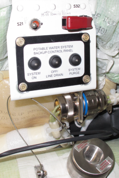
PWS Backup Control Panel
The (EIB) control panel is located above the water storage tank. The PWS backup control panel provides control over the water system functions in the event the TSE is not functioning properly. PWS mode selection through the backup control panel can be done whenever PWS servicing through the ESP is not being performed.
The panel has three pushbutton switches with integral LED indicators to reflect the active PWS mode and allows the user to select SYSTEM ON, OFF/ LINE DRAIN, and SYSTEM PURGE modes.
The backup control panel can be used in flight or on the ground. The external service panel, however, will have priority over this panel when the aircraft is on the ground.

Water Heaters
The 115 VAC electric water heaters provide hot water to the galley and aft lavatory sinks. They are controlled by the galley TSE and contain sensors that are used to remove power from the units when water is not available. Each unit contains three cartridge heaters, a pressure relief valve, an over-temperature protections circuit, a water level sensor, a water temperature sensor, and a temperature selector switch.
Three temperature settings are available:
- Low 46 °C (115°F)
- Medium 57 °C (135 °F)
- High 68 °C (155 °F)
The built-in control circuitry prevents operation with no water present, and has a thermal shut-off device in case the primary control fails, or if the water temperature exceeds 90.5 °C (195 °F).
Manual reset can only be accomplished by removing the top heater cover.
The heaters have an On/Off switch an a power indicator.

05/19/16
Water Pumps
Two continuous duty water pumps are used to constantly circulate water throughout the system. They are centrifugal-type pumps and are installed below the water tank. The PWS uses two water pumps, each installed on either side of the pump selector valve. The pump supplies potable water from the water storage tank, through the water sterilizer, to the galley and lavatory sinks and to the lavatory toilets. Unused water will go back to the water storage tank.
These 28 VDC pumps supply up to 40 psig at 2.5 gpm (9.5 liters per min). A flow restrictor installed at the aft lavatory maintains a minimum water pressure of 25 psig.
To ensure constant priming of the pump, the pump is located below the tank waterline. The PWS uses one pump at a time during System Purge and SYS ON modes requiring pump operation. The second pump serves as a backup. To maximize pump life, the pumps switch roles as primary and backup every time the FILL operation is performed. The pumps are not active during Fill or Off / Line Drain mode.
The EIB uses a pressure transducer - pressure signal to monitors pump operation and detects water pressurization faults. The transducer is a silicon-on-insulator pressure sensor. The transducer is installed between the water pumps and the water sterilizer. The transducer receives a 10.0 VDC voltage input supplied by the EIB and produces a differential output voltage proportional to the sensed pressure. The EIB automatically switches to the backup (second) pump in case of failure.
Caution:
The pumps should not be operated dry.


GLOBAL 5000 INSTALLATION

GLOBAL EXPRESS XRS INSTALLATION
05/19/16
External Water Service Control Panel
The External Water Service Control Panel located on the right aft fuselage side, aft of the right wing fairing, the fairing by the right engine, provides external control over the water system functions, including four-position rotary switch to allow the selection of FLIGHT, FILL, LINE DRAIN, and PURGE. The ESP switch has a Flight position to control the CES and backup control panel when the aircraft is on the ground and the service panel door is open.
Water level indication is provided by five LED indicators on the panel. Each of the level indicator's LED's are green in color, except for the empty LED which is amber.
A selector switch is used to select the mode of operation. On the ground, the External Water Service Control Panel has priority over the galley TSE, and the backup control panel, for control of the water system.
When the access door to the panel is opened, the Status indication 'External Service' is shown on the galley TSE. The ESP area contains a switch that activates and deactivates upon service door opening and closure. The switch signal provides input to the EIB controller and is used to inhibit the service mode selection when the door is closed. The switch enables PWS mode selection when the door is open and the WOW indicates that the aircraft is on the ground.


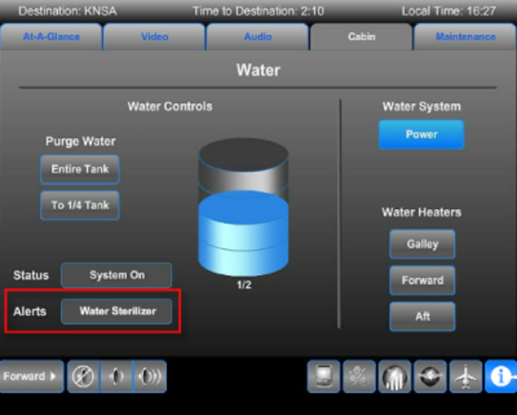
Control and Monitoring
Control and monitoring of the water system is through the galley Touch Screen Equipment (TSE).
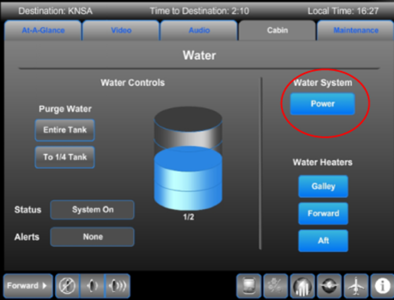
Under the Cabin content category, selecting the Water icon will display the Water page. An analog and fractional indication of water quantity is presented in the center of the page.
Controls are provided for:
- Purging of the tanks and lines
- Power application
- System status and alerts
- Water heater selection

Lavatory Water Supply
The water supply to the lavatory is controlled by a motorized valve with a manual override lever. The motorized valve is operated by a floor mat switch through the EIB. When a passenger steps on the switch, water flows to the tap. When the passenger leaves the compartment, the water supply is cut off.
The manual override lever provides a means to force the valve closed in the event of system failure.
The sink drain is controlled by a manual shutoff valve operated by the manual shutoff control lever at the sink.
Note:
The vent valves are only used during line drain.
Galley Water Supply
The water supply to the galley is controlled by a motorized valve with a manual override lever. The motorized valve is operated by a tambour door microswitch through the EUB. When the tambour door is opened, water is available to the galley faucets. When the door is closed, the water supply is cut off.
The tambour door switch is designed to prevent water damage if the faucets were inadvertently left On.
The galley shutoff valve manual override lever provides a means to force the valve closed in the event of valve failure.
The galley sink drain valve is controlled by an electrical signal from the SINK DRAIN button.

System Operation
The EIB (Electronic Interface Box) provides control and fault monitoring for the water system and freeze protection components. It is interfaced to the Cabin Electronics System (CES) where control and fault signals are transferred. The water system and EIB are controlled via the galley touchscreen (CES), the external service panel (172BR), and the backup control panel. During flight, the PWS is controlled via the galley touchscreen. The Backup Control Panel is used when the CES is inoperative. The external water service panel is active only when the panel door is open. Touchscreen and Backup Control Panel use is disabled when the external service panel is active.
Dual water pumps circulate potable water throughout the water system. One pump acts as a primary pump while a second water pump acts as a stand-by pump should the primary pump fail. The pumps alternate as primary and secondary each time a FILL operation is performed.
During System ON mode, the water is constantly re-circulated throughout the aircraft. The water is filtered and sterilized by a water filter assembly containing an activated charcoal filter and an ultra-violet lamp. Electrically operated motorized valves are opened and closed based on pre-programed settings stored in the EIB. Water supply to the lavatory or galley sink is controlled by motorized valves that are activated by a floor mat switch or the tambour door switch. This allows water flow to a lavatory sink only when the lavatory is occupied, and to the galley sink only when the tambour door is opened.
System FILL
During system fill, the motorized valves route the external fill port to the tank to allow it to be filled. This mode is entered when the aircraft is on the ground, the external service door is opened, and the external mode selector switch is placed in the FILL position. The mode switch on the external panel has a time delay of approximately 3 seconds when selecting a function. If aircraft generated power is not available during System FILL, the PWS will operate from battery power for up to 1 hour, at which time the system is de-energized to prevent battery depletion. The successful completion of a fill procedure will cause the two water pumps to switch primary and stand-by roles. This is done to prevent wear on one pump.
There is an additional manual filling method available inside the aircraft during the system ON mode. In this procedure the manual fill port of the tank is opened and water is manually added.
Filling the water system through the fill port and applying pressure.
When the SYSTEM MODE selector is set to FILL, the fill valve and the drain valve rotate. Water is forced into the water tank. Lights on the service panel indicate increasing water level. When the tank is to be completely filled, water will run out of the drain mast.
The water supply should be shut off, and the lines allowed to drain, before returning the SYSTEM MODE selector to the FLIGHT position.
FILL PORT AND SYSTEM MODE SELECTOR
System ON/FLIGHT
The ON mode is the normal flight mode of the PWS. The EIB performs a water level check to allow operation when selecting system ON. If the water level is below minimum levels, the PWS enters the OFF/LINE DRAIN mode for protection.
In the ON mode, a single pump operates to provide system pressure, and recirculates the water through the system loop. The water freeze protection heaters are activated as required to prevent freezing. The water pressure is monitored for proper system performance. The water is circulated through the water filter assembly for sterilization. The system can be manually enabled to remain functional if the sterilizer fails, and will report the condition on the galley touchscreen.
Note:
The potable water system retains the maximum quantity of water when the water tank is filled following SYSTEM ON/FLIGHT mode. If the water tank is filled following OFF/LINE DRAIN mode, the water tank level will be lower by approximately 2.70 U.S. gallons (10.22 liters) due to water from the tank filling the empty distribution lines when switching from FILL to SYSTEM ON/FLIGHT mode. Because of this, the water level indication will indicate less than FULL. The next level below FULL is indicated on the galley TSE, or the external service panel, to be 3/4. The actual water level is between 3/4 to FULL when 3/4 is shown on the galley TSE or the external service panel.
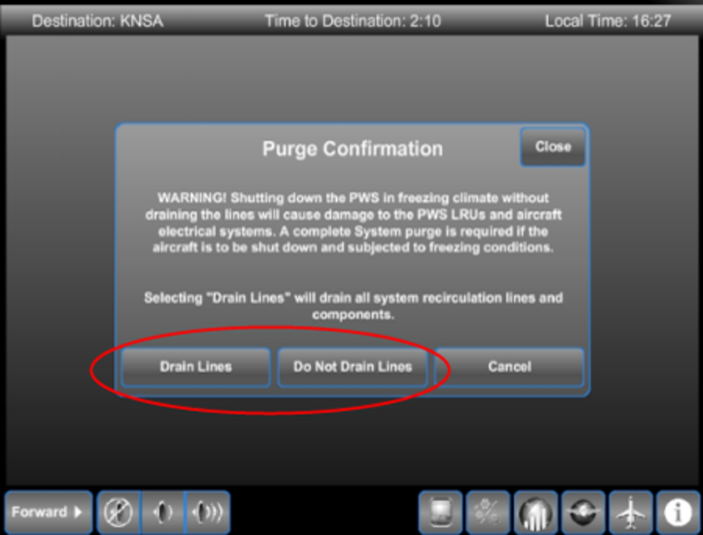
OFF/LINE DRAIN
When the PWS is set to OFF, a dialogue box appears. This warns the operator to consider the option to drain the water lines.
If 'Do Not Drain Lines' is selected, the water system will power down with all drain valves in the closed position, preventing the draining of water from the lines. A message Off-No Line Drain is displayed.
If 'Do Not Drain Lines' is selected and the CES remains powered, the water system automatically switches to the 'System On' mode when the aircraft becomes airborne.
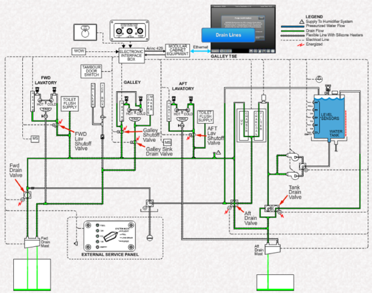
If 'Drain Lines' is selected, the water system will power down with all drain valves in the open position. A quantity of water, no more than 2 U.S. gal (7.4 Liters), will be lost from each drain mast.
During draining, gravity us used to empty the entire water system, except for the tank(s). Water is drained through the forward and aft drain masts. When the water system is selected OFF, and the drain Lines option is selected, the water pump is turned off. The galley and lavatory shutoff valves, the galley sink drain valve, and the forward and aft drain valves are opened.
The tank drain valve is first selected to the overflow position for 45 seconds then rotated to the drain position.
Vent valves open to allow air to enter the lines. After 5 minutes, all valves close.
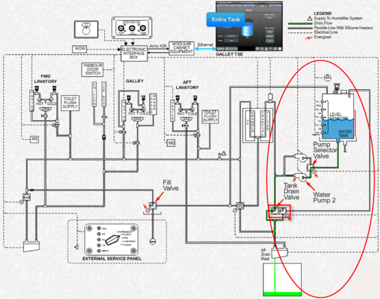
System PURGE
This mode drains the water system lines, components, and tanks. When entering this mode valves are actuated to the drain position, and the pump is activated until the water level in the tank falls below empty. The pump is then deactivated and the remaining water drains by gravity. The drain valves close 5 minutes after the pump stops. The system purge mode may be selected from the galley TSE, the Backup Control Panel, and the external service panel.
During purge mode, the EIB powers the primary pump. The tank drain valve is selected to the overflow position for 45 seconds, then to the drain position. Water is forced out of the aft drain mast.
The fill valve is closed to prevent the water form recirculating back to the tank. All other valves are closed during purging. 270 seconds after the tank is empty, the EIB will operate the backup pump an drain any remaining water for 30 seconds, then rotate back to the active pump. After this, the line drain mode is automatically entered for 5 minutes to clear any residual water.
When PURGE mode is selected, the maximum amount of water that can be expected to drain from the water system is approximately 41.3 U.S. gallons (156.34 liters). 38.6 U.S. gallons (146.12 liters) will drain from the two water tanks when full and about 2.70 U.S. gallons (10.22 liters) from the distribution lines. Approximately 1.45 U.S. gallons (5.49 liters) of the water from the distribution lines, and the water from the water tank, can be expected to drain from the aft drain mast, while approximately 1.25 U.S. gallons (4.73 liters) of water can be expected to drain from the forward drain mast.

Purge To 1/4 Function
This mode partially drains the water tank to one fourth of its capacity. The potable water system will continue to run in the system ON mode with about a quarter tank of water. This feature allows the operator to purge most of the water from the tank in flight and minimize the amount of water drained on the ground after the aircraft has landed.
Purging differs from draining. During purging, the water pump is used to empty the water tank. During draining, the water tank is not emptied.
The 1/4 Tank mode is used when preparing for landing to reduce the amount of water that must be purged on the ground. When complete, the system automatically returns to the ON mode.
On ground, the system can be fully purged if so desired.

Valve Override Operations
CAUTION:
OVERRIDING THE MAT SWITCH OR TAMBOUR DOOR SWITCH BY MANUALLY SWITCHING THE MOTORIZED VALVE WILL NOT PREVENT A WATER SPILL IN THE CASE WHERE FAUCETS ARE LEFT OPEN AND THE SYSTEM IS POWERED UP AND RUNNING OR IF THE WATER SYSTEM IS SERVICED.
The lavatory and galley water supplies incorporate motorized valves that are opened when the mat or tambour door switches are activated. In the event of a valve failure or system malfunction, the switch can be overridden by manually turning the valve using the handle on the unit. This action ensures water can continue to flow to the faucets.
Manually opening the motorized valves overrides the safety feature provided by the switches, and even though water can flow to the faucets, this feature should only be used for dispatch purposes, and water system troubleshooting should occur as soon as possible.