


05/20/16
Overview
The Cabin Electronics System (CES) is integrated with passenger and selected crew systems for control of cabin functions and maintenance reporting purposes. The CES is a complete package capable of managing a variety of source equipments and functions, from entertainment sources and environmental systems to the high speed data link communications used for global office features. This system offers built-in centralized diagnostics to facilitate simple service and maintenance. The system consists of controllers, a centralized processing center, distributors, and receivers. Note that the system configuration described herein is of a typical aircraft installation and may not reflect your installed aircraft options.
CES is an integrated control, display, and maintenance system for the aircraft cabin systems and equipment. It provides centralized control, signal routing, and network integration, utilizing an Ethernet network as the primary system data bus for following functional system groups:
- Global Office
- Cabin Utilities
- Power Distribution
- Entertainment
- Cabin Services
- Control Display
- Maintenance and Diagnostics
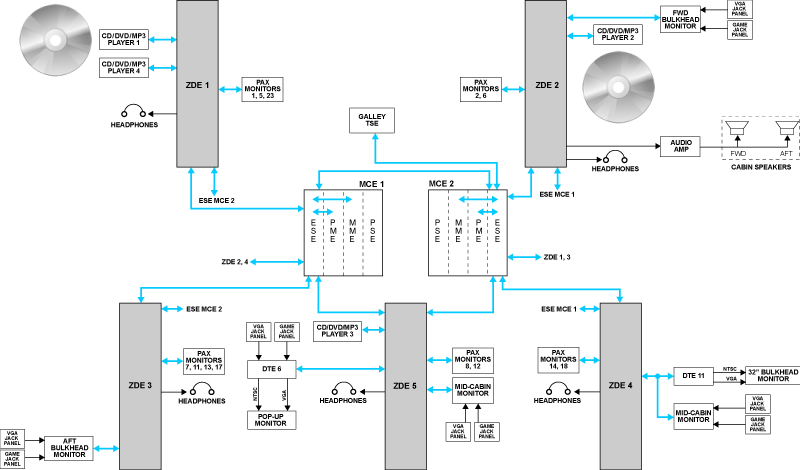
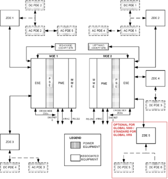
The backbone of the CES consists of two Rockwell Collins MCE-6000 Modular Cabinet Equipment units that provide processing resources, and an ethernet databus with two ESE-6100 ethernet switches and four ZDE-6000 zone distribution units. The two MCE-6000 cabinets provide dual redundant processing and provide modular bays for convenient removal and installation of additional modular CES functions such as audio and video on demand. The databus provides signal routing for the following types of information:
- Command and control signals
- Digital entertainment audio and video
- Internet access
- Maintenance and diagnostic information
- File transfers
The MCE-6000 cabinets contain the following modular equipment:
- MME-6000/6100 Moving map equipment
- PME-6000 Processor/Mass storage equipment
- PSE-6000 Power supply equipment
- ESE-6100 Ethernet switching equipment
The CES supplies power for the baseline security system battery charger. The CES controls the optional security system digital video recorder (DVR) using discrete signals from the MCE. The CES communicates to the camera system video control unit (VCU) through a RS-485 data bus. The CES displays camera and security system video from each camera to the cabin monitors, the cockpit electronic flight bag (EFB), and the touch screen equipments (TSE).
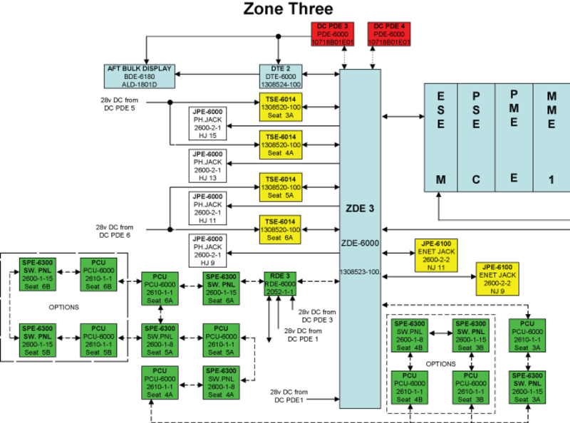
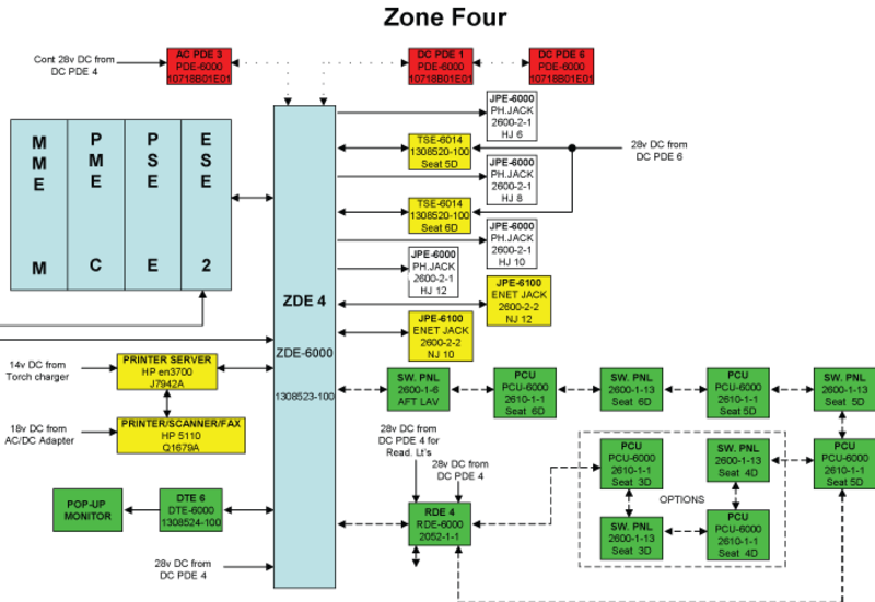
The CES is interfaced to various aircraft cabin systems and equipment via the four ZDE-6000 zone distribution units. They provide a direct interface to equipment that is databus compatible. The ZDE-6000s connect to analog equipment via RDE-6000 relay drive units which route analog control and power signals to and from various equipment.
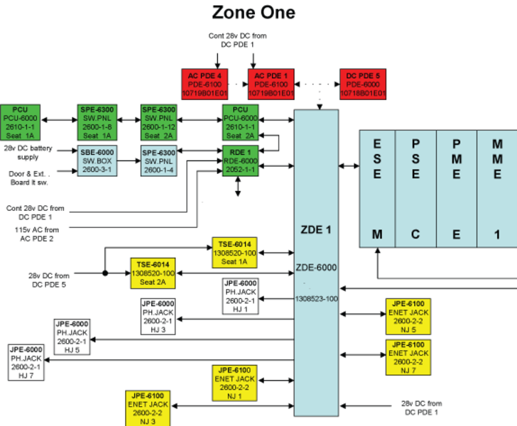
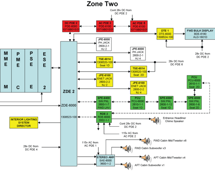
Equipment shown boxed in red are optional for Global 5000, and standard equipment for Global XRS.


05/20/16
System Backbone
The system backbone forms the spine of the CES to which all other systems are connected.
System processing is done in dual redundant processing cabinets. The two MCE-6000s host the core set of processing resources (processor, memory, I/O). The MCE contains a set of modular resources that can easily be installed or removed as required. The modular resources are intended to support the optional functionality, for example audio and video on demand. The primary system data bus uses a 10/100 Base T Ethernet network.
The Ethernet network is distributed through the cabin using the network distribution equipment. This network is essentially Ethernet Switch Equipment (ESE), with additional functionality included for digital distribution of entertainment. The two ESE-6100s (located in the MCEs) and the four ZDE-6000 Zone Distribution Equipments make up the network distribution equipment.

MCE-6000 Modular Cabinet Equipment
The MCE is the core of the CES. Two cabinets are installed in the aircraft. The two cabinets are not completely redundant, since some external systems are only connected to a single cabinet. Therefore the loss of the cabinet associated with a single external system will result in loss of control or interface to that external system. The MCEs are dual, redundant processing cabinets that provide all of the system processing, memory, and I/O functions through independent modules.
The cabinet consists of a mechanical structure and a rear interconnect (motherboard) circuit card assembly (CCA). The MCE is bolted directly to aircraft structure. The MCE is designed for forced cooling air flow. The fan assembly is mounted directly under the MCE, on the underside of the mounting plate, to provide cooling air for the MCE.
The MCE-6000 is the physical cabinet that holds the MCE modules. The MCE-6000 Modular Cabinet Equipment houses the four modules that follow:
- MME-6000/6100 Moving Map Equipment
- PSE-6000 Power Supply Equipment
- PME-6000 Processor/Mass Storage Equipment
- ESE-6100 Ethernet Switch Equipment.
- MFE-6000 MCE Fan Equipment
The use of an MME module is optional. The MCE provides for a cover plate at the MME position. If the MCE is not populated with an MME, the optional cover plate is installed in the cabinet.
See the System Interface section below for the MCE interface.


MME-6000/6100 Moving Map Equipment
The Moving Map Equipment (MME) is installed in the MCE, but is not part of the system backbone. The MME provides a processor that is independent from the basic cabinet processor. The MME processor and hard disk host the software applications such as the airshow moving map, audio on demand server, and Video On-Demand (VOD) server. The MME-6000 has a single hard drive. The MME-6100 has dual hard drives.
The MME processor and hard drive(s) hosts:
- Software applications for the airshow moving map display
- Passenger briefings
- Printer drivers for non-standard printers (if required)
Although there are provisions for two MMEs, many aircraft do not install an MME in MCE 2.
The MME communicates over an internal ethernet line with the PME. The MME also communicates with external CES devices via the ESE. The MME's software is loaded independently from the PME software using the File Transfer Protocol (FTP) with the maintenance laptop.
To support the airshow moving map application, the MME is supplied with environment data (altitude, speed, etc.) and position data (latitude/longitude) from the FMS. This ARINC data is processed by the PME which it forwards to the MME through an Ethernet connection inside the MCE. The MME data terminal interface provides an RS-232 serial data connection to an onboard modem. This interface provides airshow updates from the Iridium communications system.
PSE-6000 Power Supply Equipment
The power supply equipment (PSE) module contains a single CCA. This assembly provides power regulation for the rest of the MCE through the MCE backplane bus. The PSE-6000 Power Supply Equipment supplies power to each module in the cabinet. Primary input power is a nominal +28 VDC form the cockpit CB panel, and regulates voltages to the proper levels required by all modules.. There is a secondary 28 VDC power input intended for an optional battery connection. The Power Supply Equipment (PSE) includes a capacitor-backed holdup capability. The primary input power may be removed for up to 200 milliseconds and the MCE continues to operate normally. This requirement applies when the PSE holdup circuit is fully charged, which is 3 seconds after power up or the last power dropout. In the case when a power dropout exceeds 200 milliseconds, the PSE will start a shutdown sequence. This provides a minimum of 3 milliseconds to shutdown the processor mass storage equipment (PME) software, and a minimum of 20 milliseconds to shutdown the MME software after the power warn interrupt is issued by the PSE.
The PSE has independent power distribution to each module. If one of the modules failed and shorted its power source, the PSE would continue to supply power to the other modules.
The PSE operation is inhibited when the temperature is less than -25 ± 5 °C (-13 °F). The PSE shuts down when the temperature is greater than +110 ± 5 °C (230 °F).
PME-6000 Processor/Mass Storage Equipment
The PME-6000 Processor/Mass Storage Equipment module provides the processing, I/O, and memory resources for the MCE. The Processor/Mass Storage Equipment (PME) is a key element in the CES system backbone. The PME provides control and communication to end devices, configuration management, graphical interface for user input and reporting, dataload services for itself and all CES end device equipment like TSE, ZDE, video encode equipment (VEE), digital tapping equipment (DTE), and MDSB.
The PME has the input/output connections that follow:
- 6 ARINC 429 Inputs
- 6 ARINC 429 Outputs
- 8 GND/OPEN Discrete Inputs
- 8 +28 VDC/Open Discrete Inputs
- 8 GND/Open Discrete Outputs
- 3 +28 VDC/Open Discrete Outputs
- Miscellaneous inputs and outputs (e.g. WOW and camera telephoto/zoom controls)
The PME is connected to the CES network LAN which represents the first level of data communication path. This connection is performed through the PME backplane bus of the MCE cabinet to the Ethernet switch that resides inside the MCE. The PME does the command and control processing for the system backbone. The PME has a processor and I/O card, mass storage card, and Ethernet node card.
The CES architecture provides another level of communication path to devices that are not Ethernet devices and that reside on different types of serial buses such as RS232, RS485 and MDSB. The PME does not communicate directly with these end-devices, but indirectly via IO mapping devices, which reside in the ZDE and VEE. Thus PME provides Ethernet LAN to serial bus communication. Hence the PME can reach any end device in the system to perform flow control, data management and software/configuration downloads.
The PME also provides three 10/100 Base T and one 10 Base T Ethernet ports. The Input/Output (I/O) and Mass Storage Unit provides I/O interface to external systems and stores most of the CES software. The Memory Mass Storage has a minimum of 2 gigabytes of flash memory.
The Node is an interface device within the PME with its own processor and software. The node controls the operation of the ESE and provides the ethernet interface between the PME and ESE.
The Node uses non-volatile memory (NVM) to store code and error tables. This is also where the golden code is stored. The golden code is a copy of the software that is uneditable by any means other than at the factory. This provides a backup copy of software to enable booting in case of failures that render the normal software unusable.
There are provisions for 6 ARINC 429 I/O to each PME. ARINC data communication with PME 1 is different from that with PME 2. Not all I/O are used.
The Galley TSE provides a utility to monitor the transmission of words on the ARINC 429 buses.
Each PME has provisions for 8 ground/open type discrete I/O. In addition, provision is made for 8 inputs and 3 outputs of the 28V/open type. These discrete signals can be monitored on the Galley TSE.
ESE-6100 Ethernet Switch Equipment
The ESE-6100 provides 24 10/100 Base T Ethernet ports, including cross-talk to the other MCE. Each MCE contains one ESE. The number 1 and 2 ESEs are connected to each ZDE. Each ZDE is physically connected to two Local Area Networks (LAN). This redundancy prevents a single failure from taking down the entire network backbone.
The ESE also provides internal ethernet communications with the PME and MME.
The ESE uses a PowerPC processor to manage ethernet traffic.
At power-up, the ESE receives its configuration file from the node of the PME for ethernet traffic management control and security, such as firewall.
The ESE supplies ethernet switch and router functions. As a switch, it forwards ethernet frames based on media access control (MAC) address (rather than IP address). As a router, the ESE supports 2 virtual LANs, each with a unique IP address.
The ESE also hosts the domain name system (DNS) and dynamic host configuration protocol (DHCP) servers.
The two MCEs operate in a master/slave relationship to provide redundancy. All ZDEs connect to both MCEs through the ESEs. Normally, the PME in MCE 1 is the master unit and continually communicates with the PME in MCE 2 through a cross-talk ethernet link.
All ZDEs normally communicate with the active PME through the associated ESE. If for some reason the communication link with the PME is interrupted, communication will automatically be rerouted through the other ESE and cross-talk link.
MFE-6000 MCE Fan Equipment
The MFE-6000 MCE Fan Equipment provides the cooling air for the MCE-6000. The Modular Fan Equipment (MFE) includes a fan, a power filter assembly, and a fan monitor assembly. The power filter assembly provides the filtering and transient protection to the fan input power. The MFE connects directly to the +28 VDC aircraft power. The fan monitor assembly detects the fan speed and outputs a status discrete signal to the PSE. The MCE temperature sensor outputs a discrete signal to the PSE if temperature is greater than +10 ± 5 °C (+50 °F). This discrete enables the PSE to close a low-side switch that connects the fan power to ground. The fan is physically separate from the MCE-6000. The cooling fan is mounted on the bottom side of the MCE mounting surface.


MCE Power Supply
MCE 1 and 2 are supplied with 28 VDC from the CB panel in the cockpit. The busses which supply these CBs receive power when the CABIN POWER switch is selected on, with AC power applied. Thus a reboot of the MCEs can be accomplished by cycling the CABIN POWER switch rather than pulling the CBs.
Note:
Pulling the MCE CBs in flight can have an adverse effect on the water system. If a reboot of the CES is required, use the CABIN POWER switch instead.
The circuit breakers that supply the MCEs also supply their cooling fans. Each fan is controlled by a thermal switch inside its MCE. The fans operate automatically. A fault monitor detects fan failure and provides indication on the Galley TSE. An in-line fuse will open in the event of short circuits in the fan circuitry. A fuse is used to avoid tripping the MCE CB for fan shorts.

ZDE-6000 Zone Distribution Equipment
The four ZDE-6000s (five for Global XRS) provide the interface between the devices in each cabin zone and the network backbone. See the System Interface section below for the definition of each zone.
A ZDE is the primary interface distribution node for a particular seating zone area. The ZDEs provide the different seating zone connectivity configurations. The connectivity configurations include the various combinations of the Passenger Touch Screen Equipment, laptop computers, and carry-on CD and DVD media sources. The ZDE contains the functions that follow:
- Ethernet Switch Router
- Controller
- Four Channel Audio Decoder
- Power Supply
The Ethernet Switch Router provides full-duplex LAN connectivity to the CES MCE. The ZDE provides up to 12 Ethernet interfaces for carry-on lap tops, Touch Screen Equipment (TSE), Integrated Lighting System Director (ILSD), monitors, CD/DVD/MP3 players, Video Encoding Equipment (VEE), Passenger Control Unit (PCU), and maintenance computer connections.
The Controller provides the processing and control of the internal and external discrete I/O and serial data bus ports. The controller also provides the operational control for the Ethernet Switch Router.
The Four-Channel Audio Decoder decodes the incoming digital-audio media streams for distribution to the passenger stereo headphones and the audio distribution system. The four channels are independent and can provide a different audio output to each headphone. The audio decoders have two, auxiliary, stereo-audio outputs. The auxiliary stereo-audio outputs provide the drive for the Public Address (PA) Stereo Amplifier.
The DC Power Distribution Equipment (PDE) provides the +28 VDC power to the ZDE power supply. The power supply has a DC/DC converter that provides the correct voltage levels for the ZDE internal circuits. The ZDE also provides the power source for the noise cancellation headphone connections. The ZDE has internal cooling fans. Some ZDEs have an optional cooling plenum to provide effective routing of cooling air.
On power up, the ZDE performs internal BITE.
When the ZDE boots, it receives configuration data from the PME it initialize ethernet communication. This data updates the ZDE with the most current information, especially if a new ZDE is installed.
The ZDE contains an ethernet switch router to connect the ZDE to the MCEs via the 'head ends', and to the cabin ethernet equipment.
An RS-232 interface is provided to the passenger TSEs and is used to assign an IP address. This is necessary so that the TSE is related to the particular seat as some TSEs are portable and could be installed in a number of cabin locations.
An RS-485 interface is provided with the PDEs in the zone. This allows communication with the PME via the ZDE. ZDE 2 also connects to the oven to provide oven control from the Galley TSE. A multi-drop serial bus (MDSB) interface is provided for switch panels, relay drive equipment and wired passenger control units (PCU) on the Global 5000 aircraft only.
The four-channel, Audio Digital Signal Processor (DSP) decodes the incoming ethernet digital audio streams into analog for distribution to passenger stereo headphones. The four channels are independent and provide separate control of the output to each headphone. Channels 3 and 4 are also connected to two auxiliary stereo-audio outputs, which provides an audio equalizer output for the cabin audio amplifier on ZDE 2 only.


Each ZDE contains a green, yellow, and red LED status indicator. These indicators are visible through the cooling holes in the cover opposite the cooling fans. If multiple conditions exist, the LED indications that correspond to the highest priority is displayed.


DE LED DEFINITIONS
Electronic Flight Bag (EFB) (Cockpit Touchscreen)
The EFB serves as a backup to the galley touchscreen. The screen content is identical to the galley touchscreen except the entertainment video is disabled.
The EFB is a very light and compact screen, daylight readability, night flight capable dimming and touch screen convenience. The unit accepts 12 - 20 VDC and has a standard Video Graphics Array (VGA), Universal Serial Bus (USB) connection for video and the touch screen. The Electronic Flight Bag (EFB) provides a back-up to the Galley Touch Screen Equipment (TSE) functions. The PME-6000 drives the EFB display, through the Enhanced Expansion Module Unit (EEMU). The EFB software resides in the PME module of the MCE.


ELECTRONIC DISPLAY UNIT

05/20/16
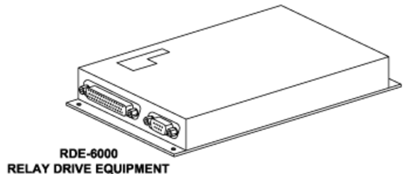
RDE-6000 Relay Drive Equipment
The RDE provides the switched relay and discrete ground or +28 VDC outputs to control the cabin components in its associated zone. Associated with each ZDE is an DRE. The RDE is controlled by the local data bus. The ZDE outputs a Multi-Drop Serial Bus (MDSB) to connect the RDEs to the network.
The ZDE controls the RDE through the MDSB bus. The majority of analog interfaces are provided via the RDE.
For systems which require only ON/OFF control, the control is provided either by the power distribution equipment (PDE) directly or through a combination of the PDEs and the RDEs.
The RDE provides control and switching functions for systems that are not ethernet compatible such as entry heaters, reading lights and electric window shades.
Each RDE includes the following:
- 14 relays
- Programmable chime
- Power supply
- Two 10K ohm digital potentiometers
- Discrete outputs
- Logical inputs and outputs
- Diagnostic display
Relays inside the RDE switch DC or AC power up to 5 amps each. These relays control reading and table lights, fans, etc.
Discrete outputs provide ground signals to control window shade operation and similar functions. Logical inputs (highs or lows) are used to provide feedback to confirm the status of certain functions, such as unlocking of the forward cabin door.
The programmable chime is used on one RDE only, normally RDE 2. This chime is used for flight attendant call.
The RDE uses a two-digit LED digital display and a number of LEDs to provide status and diagnostic information.


RDE Diagnostics Indications


When a selection is made, the TSE sends the request to the PME via ethernet. The touch screen button highlights to indicate that the request is being processed. Since the end-device is on the MDSB, the PME tunnels the data inside ethernet packets to the associated ZDE. The ZDE input/output processor (IOP) converts the request to an RS-485 signal path which is sent via the MDSB to the RDE. The RDE will activate the relay which routes 115 VAC to the floormat heater.
The RDE sends a signal back to the PME to confirm that it has received the command. If this feedback is not received, the PME will remove the highlight from the button.

The RDE is also used to control cabin temperature. Selecting an increase or decrease of cabin temperature on the Galley TSE will operate dual digital potentiometers in the RDE. The air conditioning system controller (ACSC) will respond to the request and adjust cabin temperature accordingly.
The sensed cabin temperature is monitored by the ACSC and sent via ARINC 429 to the PME which displays it on the touch screen.


05/20/16
RJ-45 Cockpit Ethernet Ports
An RJ-45 Ethernet port is located in each side console of the cockpit. These ports allow the connection of a laptop computer for maintenance purposes. The RJ-45 jack panel sub-assembly is interfaced with the Ethernet LAN and provides access to the LAN to passengers.

05/20/16
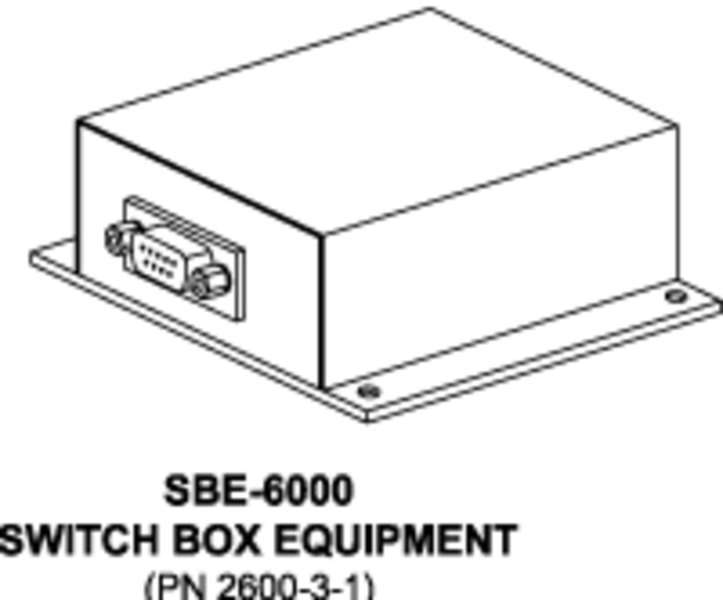
SBE-6000 Switch Box Equipment
The switch box equipment provides or removes power to the boarding lights, baggage lights, and pylon lights. The SBE consists of a hermetically sealed latching relay and a microprocessor equipped with flash memory, which act as a SPDT switch. The microprocessor responds to a momentary ground input to change the state of the latching relay based on the last known state saved in flash memory. This action will make or break the connection of power to incandescent or fluorescent lights.
05/20/16
SPE-6100/6300/6400 Switch Panel Equipment
The SPE-6100/6220/6300/6400 Switch Panel Equipment provide the passenger switch panel controls. The Switch Panel Equipment (SPE) provides controls for the attendant call, reading lights, various other lighting, and toilet flush. Switch panels are hard mounted in the cabin side ledge, cabinetry, arm rest, or bulkhead.
SPE are located throughout the cabin to provide switching functions.

Multi-Drop Serial Bus
The multi-drop serial bus (MDSB) connects switch panels and RDE to the ZDE to interface these units with the CES. The MDSB physically connects the panels and the RDE in a daisy-chain to the ZDE. Should a disconnect occur, the downstream components would be inoperative while the upstream components would still function normally.
However, in operation, the interface of each unit with the ZDE is as shown here. The name "multi-drop" refers to multiple units that "drop" from the serial bus. Each unit has a direct line of communication with the ZDE. It does not matter in which order the units are wired as long as they are addressed correctly.
To identify units on the MDSB each unit must be individually addressed. The typical means of addressing is to ground or strap specific unit pins. Switch panel equipment however are addressed in a unique manner. Located on the back of the switch panel are 3 rotary switched. The combination of the switch positions determines the address of the unit.
A table, unique to each aircraft, provides the addressing assignments for each of the switch panels. When replacing a panel, it is important to take note of the switches an set the replacement panel to the same positions. Incorrectly set switches may render the new panel inoperative.


05/20/16
TSE-6014 Touchscreen Equipment
The TSE-6014 touchscreens provide a user interface to the CES where various cabin systems are controlled and maintenance functions can be performed. The galley touchscreen is the primary CES Built-In-Test (BIT) and diagnostic interface. The TSE consists of a video controller electronics assembly, a touch screen LCD assembly, and DC/DC converter.
The TSE can be used for the following in-flight entertainment (IFE) system functions:
- Passenger viewing of digital video entertainment sources
- Galley and VIP passenger cabin displays for monitor and control of IFE functions
The electronic flight bag (EFB) provides the pilot interface to control the interactive moving map, show the system status information, and provide the system control function. The TSE connects directly to the CES Ethernet communications backbone through a ZDE to receive and decode MPEG-1, MPEG-2 or MPEG-4 audio and video media streams generated by the IFE source. The unit provides display of video entertainment selections, web pages, and display adjustment control menus.
A single Galley Touch Screen Equipment (TSE) provides the highest level of user control. The Galley TSE interfaces directly with modular cabinet equipment (MCE) 2 which enables it to continue operating regardless of any failure of a zone distribution equipment (ZDE).
Each zone can support up to four passenger TSEs, the limit imposed by the ZDE. Some of the passenger TSEs can be configured as master seat location (MSL) TSEs which provide zone control in contrast to the local control of a passenger TSE/PAX monitor.
The TSE is essentially a computer with a touch interface. The TSE loads the CES graphic/user interface (GUI) in a commercial browser, i.e. Internet explorer, from the processor mass/storage equipment (PME) during power-up.
A photo sensor switch on the rear of the 10.4 inch unit automatically shuts off the unit's backlight if a reflective surface, e.g. glossy white or metallic, is within 1.0 inch. Depending on the sensitivity and reflectivity of adjacent surfaces, the backlight might be shut off if the reflective surface is within 3.0 inches.
The TSE is provided with 28 VDC for operation and the backlight inverter which powers the LCD display. An ethernet switch routes ethernet communication between the PME and the TSE's processor/video controller and audio encoder.
On boot up, the TSE receives the GUI page from the PME and displays it on the LCD using the Internet Explorer web browser.
Touch selections are monitored by the TSE processor which forwards the commands over ethernet to the PME. Network addressing of the TSE is provided by the strapping of 4 pins. The strapping information is sent via RS-232 serial bus to the ZDE to allow the PME to assign an IP address.
The video controller decodes the MPEG digital media streams distributed over ethernet. The controller sends the video to the LCD allowing the TSE to display any video stream distributed over the cabin ethernet network including movies, SAT TV and camera views.
If the digital media stream also includes audio, the audio signal is re-encoded into pulse code modulation (PCM) format by the audio encoder where it is packetized and sent over ethernet. At the ZDE, the audio is decoded where it can be heard over the headphones or cabin audio system.
The new 10.6 inch, high definition Touch Screen Equipment (TSE) uses an integral micro-electronic mechanical system that senses the orientation of the unit. When oriented as stowed, the display will be turned off. The HTSE add a light sensor on the front of the display bezel. This sensor automatically adjusts display brightness with ambient lighting. The HTSE also has provision for manual brightness adjustment.


05/20/16
Video Encoder Equipment
The VEE receives audio and video signals from various source equipments and encodes them into a digital format for use over the LAN. The VEE is a multi-input, high quality video network device providing MPEG-1 and MPEG-2 encode technology over high speed IP based networks.
The VEE contains two types of circuit cards, an audio encoder board which includes the controller and two video encoder boards. Each VEE can receive four audio/video inputs and four audio only inputs. It interfaces with audio/video source equipment such as XM Radio system, portable audio/video devices, camera system, security system, and SAT TV systems. The VEE has analog video to address a wide range of interfacing IFE equipment. It supports both NTSC and PAL formats for encoding.
It operates using cabin 28 VDC power. A single VEE provides eight channels of encoding. Four channels are audio only and four channels are audio and video. The encoded outputs of the four audio and four video/audio channels are switched out onto a single Ethernet port for network connectivity.


05/20/16
Wireless LAN
The wireless LAN unit (WLU) provides wireless connectivity throughout the airplane cabin to devices that have a wireless capability that meets the regulatory and wireless fidelity (Wi-Fi) standards. It is Ethernet connected with CES and utilizes direct sequence spread spectrum (DSSS) transmitter/receiver module communicating in the 2.4 GHz radio frequency spectrum. The DSSS communication mode is 11 Mbps for IEEE 802.11b, and 54 Mbps for 802.11g. The WLU is a standalone unit allowing for flexible data communication system implemented as an extension or alternative to a wired LAN.
The Wireless LAN antenna is a directional antenna operating in the frequency band between 2.4 GHz and 2.5 GHz, right hand circular polarization. It interfaces with the WLU through an RF 50Ω coaxial cable.
Wireless Passenger Control Units
The wireless Passenger Control Units (WPCU) provide passengers with control over various seat location functions such as entertainment audio and video, temperature, and lighting.
The WPCU is a handheld touch screen device providing remote control of the CES functions. The WPCU is a HP PDA loaded with special application software. It interfaces with the CES through the wireless LAN unit.
There are four varieties of WPCUs:
- The Entertainment WPCU has the greatest functionality
- Content categories include video, audio, and cabin
- Controls all cabin zones
- The MLS WPCU is almost identical to the entertainment WPCU
- It controls only one zone
- The Crew WPCU (Global XRS only) controls the crew rest area
- the Passenger WPCUs provide local passenger audio control
Power converter units convert 28 VDC power to 5 VDC power supplied to the PCU charging cradles.


05/20/16
Wired Passenger Control Units
The wired Passenger Control Units (PCU) provide passengers with control over various seat location functions such as entertainment audio and video, temperature, and lighting. The passenger control unit is normally stowed under a door and would connect to the network via a retractable tether. To use this device the passenger opens the door, extracts the device and enters the control inputs.

Telephone System
The telephone system included as part of the CES is the ICG system that is essentially a totally stand alone system. The level of integration between the CES and the telephone system is limited to the connection of an analog telephone line to the printer/fax, annunciation of incoming faxes on the galley screen(s) and cockpit touch screen, CTU health and SATCOM voice available discretes, an RS-232 connection and iridium channel available discretes to the MCE for airshow network and fax annunciation reset and credit card enable discretes from the CES to the telephone system. Refer to ATA 23-14-00 for details on the Telephone System.
05/20/16
Ethernet Converter ( On Global XRS only)
The Ethernet converter connects the basic aircraft CAIMS PMAT laptop diagnostic device to the CES Ethernet bus to allow printing to optional printers.

05/20/16
Control and Display
The CES provides multiple control display devices to allow the cabin crew, passengers, and flight crew to interact with various cabin systems. The control and display devices are located in the galley, each seat in the cabin, various other cabin locations, and in the flight compartment. The control and display devices are as follows:
Galley TSE
The Galley TSE is the primary interface to the CES. The Galley TSE is capable of executing a commercial browser (for example, Internet Explorer). The cabinet processor serves up the web pages to the TSE. This allows the system to be fully exercised with a normally equipped laptop computer during initial installation. The Galley TSE provides super VGA resolution (800 x 600) and is capable of MPEG decoding. The aspect ratio is 4:3.
Flight Compartment TSE
The Flight Compartment TSE provides the pilot interface to control the interactive moving map, show the system status information, and provide the system control function.
Switch Panels
There are basically four types of switch panels in the system:
- Master Seat Location - PCU With Liquid Crystal Display (LCD) Screen
- Normal Seat - PCU With LCD Screen
- Local - Integrated
- Local - Non-integrated
All the switch panels are hard mounted into either the cabin sidewall ledge, cabinets, arm rest, or a bulkhead. Where PCUs are utilized, there is also a hard-mounted panel with fixed switches for reading light, table light and CALL control. All other control functions are set on the PCU. The PCU is normally stowed under a door and would connect to the network by way of a retractable tether. To use this device, the passenger opens the door, extracts the device and enters the control inputs. The audio headset jack is also under the door covering. The seat mounted switch panels also have an audio headphone jack. The first three types of switches (listed above) connect directly to the network. The local switch panels are ones in which the switch outputs are connected directly to a local control function and are not integrated. Functions controlled by local switch panels are not controllable elsewhere. A non integrated local switch would be a switch that does not connect directly to the local data bus and it does not connect directly to the device to be controlled. The output instead is routed to the CES (e.g., MCE) to allow multiple methods of control.
Wireless Remotes
The baseline system includes two wireless remote controls. These devices are not limited to controlling the entertainment system. The RF/IR interface unit converts RF remote control codes into IR control codes to the entertainment source equipment. They provide a very wide range of control functionality. The remotes are based on the existing airshow Pronto wireless remotes. The remotes are configured so that bulkhead monitor screen control commands (e.g., brightness) are issued as Infrared (IR) commands. These commands are received by and interpreted by the IR receiver in the bulkhead. All other remote control commands are issued as RF commands. These commands are received by the airshow remote controller and sent to the PME in the MCE. Source equipment commands are regenerated as IR commands in the PME and input directly to the source equipment. All other commands are output from the remote controller as MDSB commands.

Bulkhead Monitors
The bulkhead monitors are optimized for display of standard computer graphics. They have a 4:3 aspect ratio. When using these monitors as remote video displays with a wide DVD player and wide screen format (2.35:1) movies, the DVD player creates horizontal black bars (letterbox) along the top and bottom of the display. Other movie formats (1.33:1, 1.66:1 and 1.77:1) are sized by the DVD source equipment to fill the whole monitor. The bulkhead monitor also has the capability to resize the image provided by the DVD source equipment.
The monitor is not directly Ethernet compatible. As a result, the system design includes the Digital Tapping Equipment (DTE) to interface the monitor to the Ethernet network. The DTE connects directly to the CES Ethernet LAN backbone to receive and decode digitally encoded video media stream sent to it by the head end media source. It operates using cabin 28 VDC power. The DTE has an Ethernet interface and does the Moving Picture Experts Group (MPEG) to NTSC conversion to show the digitally distributed video content. The DTE also re-encodes the audio stream and routes the digital audio directly to the appropriate ZDEs for generation of headset and/or cabin speaker audio.
The monitor has both NTSC and VGA inputs. One dedicated port is provided to allow laptop connection to the monitor. These ports connect directly to the VGA input on the monitor, thus bypassing the Ethernet bus. The DTE provides the source selection for both ports. The DTE audio output is provided as regenerated digital audio to the Ethernet interface. The default condition is the NTSC input having priority on power-up.


Analog Bulkhead Monitors
The analog bulkhead monitor is a conventional LCD display. It is powered with 28 VDC and incorporates a backlight inverter for the LCD panel. A remote control unit provides on-screen display (OSD) control through an infrared (IR) sensor. The LCD monitor can display analog composite video, such as NTSC, as well as VGA video. To view digital video on the analog monitor, a DTE converts the MPEG video signal, carried over ethernet, into NTSC format for display.
Non-ethernet inputs, specifically NTSC and VGA video from carry-on equipment, are routed through the DTE without processing, directly to the monitor. On/Off control is provided via the DTE. The control signal is provided over ethernet from the Galley TSE.

Ethernet Bulkhead Monitors
The ethernet bulkhead monitor (eBDE) is essentially a modified conventional analog monitor with the functions of the DTE built in. Most eBDEs can be powered with 115 VAC instead of 28 VDC. The eBDE can also support component video required for higher quality video, such as from Blu-ray players. On-screen display control is provided by an RS-232 link. OSD commands from the Galley TSE are routed via ethernet.
In operation, a digital media file from a DVD player would be received in the DTE. The MPEG decoder separates the audio and video signals. The video signal is sent to the LCD panel as NTSC composite video.
The audio signals are re-recorded and sent back over the ethernet to be decoded in the ZDE for playback over headphones of the cabin audio system. Composite NTSC video, VGA video, and component video go directly to the monitor when that source has been selected. The monitor will automatically sense the format and resize to fit the screen.

Personal Monitors
The personal monitors are optional. All personal monitors are self-contained TSE. The baseline offering (optional) is a 10.4 in diagonal screen. The TSE is available in a variety of mounting options (plug-in, retract into seat arm-rest, articulating arm, etc.). The standard option is a plug-in mount that allows a display to be installed into a pre-wired receptacle in the cabin sidewall ledge.
System Operation (Version 7)
- Basic Operation for Ethernet Equipment
- Basic Operation for Non-Ethernet Equipment
- Key Operating Features
- Shortcut Controls and User Types
- Touch Screen Equipment (TSE)
- Cabin At-A-Glance Function
- Favorites Function
- Video Function
- Monitors Selection
- iPod Selection
- Audio Function
- Headphones
- Cabin Function
- Maintenance Function
- Diagnostics
- Configuration
- Service
- Circuit Breakers
- Network Settings
- Tests
- System
Basic Operation for Ethernet Equipment
For ethernet-compatible equipment, such as CD/DVD player, when a selection is made on the Galley TSE, the command is sent to the PME through the ESE. The PME processes the request. The PME then sends the instruction over the ethernet, through the ESE, to the ethernet switch in the ZDE, and then to the CD/DVD player. The player receives the command and starts to play.
Since the PME contains the central processing resource, it handles almost all control signals. Thus the Galley TSE must communicate with the CD player through the PME, rather than provide commands directly to the CD player.
Basic Operation for Non-Ethernet Equipment
The PME communicates with serial bus devices, such as PDEs and RDEs. These devices are not ethernet-compatible. RDEs are used to control lights, cabin temperature, galley fans, window shades, etc.
The PME uses a tunneling process to communicate with serial bus devices, allowing them to operate as if they were ethernet compatible. When a Galley TSE selection is made, the command is sent to the PME over ethernet. The PME processes the request an encapsulates the serial bus command in a tunneling protocol. This protocol wraps the command signal within an ethernet frame to allow it to travel over ethernet. The ZDE's I/O processor strips off the ethernet header an routes the serial bus signal to the end device.

Key Operating Features
- The cabin utilities give a central control for all the normal cabin lighting, services, and controls
- The entertainment system produces Compact Disk (CD) quality audio and Digital Video Disk (DVD) quality video in the cabin
- The Airshow feature provides a flight tracker and real-time data communications that allows the passenger to monitor news, sports, stocks, and weather information
- The Global Office suite provides a similar level of functionality as is found in a modern office environment
- Maintenance functions give system monitoring and controls for the flight attendants and crew. Built-in centralized diagnostics facilitate simple, minimally invasive service and maintenance
- The Touch Screen Equipment (TSE) user interface provides all the control the individual needs for managing the cabin including lighting, heating, air conditioning, window shades, and entertainment / information systems
- The Wireless Passenger Control Unit (WPCU) user interface provides personalized control of the local seat environment and entertainment functions
- The PCU user interface provides personalized control of the local seat environment and entertainment functions
- The Pronto Remote is a wireless, hand held control unit that supplies the passengers and crew with remote access to lighting, window shades, and entertainment systems
Shortcut Controls and User Types
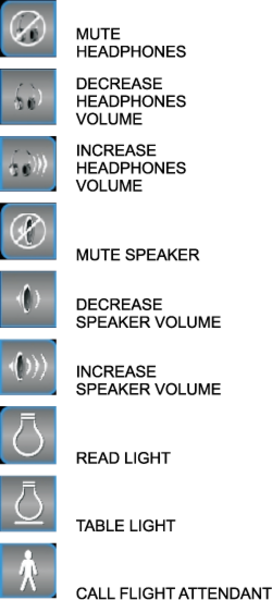
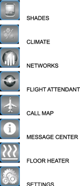
Symbols
These are the definitions of the CES common control shortcut symbols.
Galley Touch Screen Equipment (GTSE) Screen
GTSE controls are organized into five main content categories: At-A-Glance, Video, Audio, Cabin and Maintenance.
Galley TSE provides shortcuts to aircraft speaker volume controls for all available zones, call map and message center along with the optional cabin shortcuts: Flight Attendant, Networks, Climate, and Shades.

Master Seat Location (MSL) TSE Screen
MSL TSE controls are organized into 4 main content categories: Favorites, Video, Audio and Cabin.
MSL TSE provides shortcuts to headphone volume controls, aircraft zone speaker volume controls, reading lights, table lights, Call light along with the optional cabin shortcuts: Message Center, Networks, Climate, and Shades.
Passenger (PAX) TSE Screen
PAX TSE controls are organized into 2 main content categories: Video and Audio.
PAX TSE provides shortcuts to headphone volume controls, reading lights, table lights, call light, settings, and an optional floor mat heater control.
Crew TSE Screen
Crew TSE controls are organized into 3 main content categories: Video, Audio, and Cabin. Crew TSE provides shortcuts to headphone volume controls.
Touch Screen Equipment (TSE)
The Touch Screen Equipment (TSE) section contains a combination of up to five of the six possible touch screen categories: AT-A-GLANCE, FAVORITES, VIDEO, AUDIO, CABIN, MAINTENANCE. Additionally, all TSE contain an AIRSHOW section and SHORTCUTS section.
The Cabin At-A-Glance feature provides the Galley user the ability to monitor up to three cabin systems at a time.
The Favorites feature provides the MSL user the ability to select up to five entertainment and/or cabin shortcuts to be added to a Favorites screen.
The Video feature provides the user the ability to locally view available entertainment video sources.
The Audio feature provides the user the ability to locally listen to available entertainment audio sources.
The Cabin feature provides the user with varying amounts of access to cabin environmental controls.
The Maintenance feature provides the user with configuration and status messages to monitor the entertainment and environmental status of the aircraft.
The Airshow feature for flight data on all TSEs provides the configured Airshow flight data on the top area of the screen to allow the user to track the flight progress, while continuing to use other CES features.
The Airshow feature provides 3 configurable selections from the following list:
Altitude, Current Date, Distance from Departure, Distance to Destination, Distance Traveled, Estimated Arrival Time, Greenwich Mean Time, Ground Speed, Heading, Latitude, Local Time at Destination, Longitude, Mach, Outside Air Temperature, Time since Departure, Time to Destination, True Airspeed, and Wind Speed. Up to three of these can be chosen for the Airshow feature.
The Shortcuts feature provides access to commonly used controls specific to the user type.
Cabin At-A-Glance Function
Example shown is on a Galley TSE.
- Touch At-A-Glance Tab.
- Touch Personalize Your At-A-Glance.

- Select up to three At-A-Glance options.
- Touch the CLOSE button to return to the main At-A-Glance screen.

- These are the At-A-Glance selections that have been made.

Favorites Function
Example shown is on a Master Seat Location TSE.
- Touch Favorites Tab.
- Touch Personalize Your Favorites.

- Select up to five Video, Audio, or Cabin sources.
- Touch the Close button to return to the main Favorites screen.

- These are the Favorite selections that have been made. Either select one of your current favorites, or touch Personalize Your Favorites to create a different group of favorites.

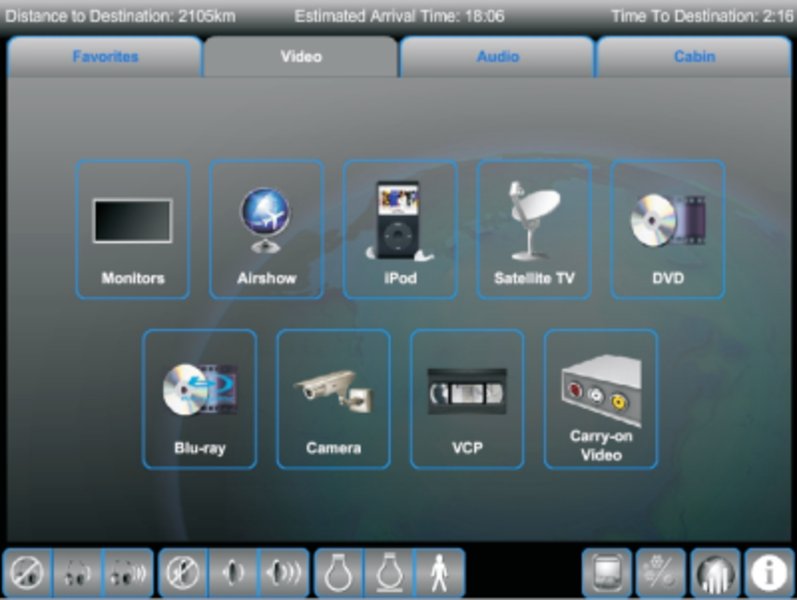
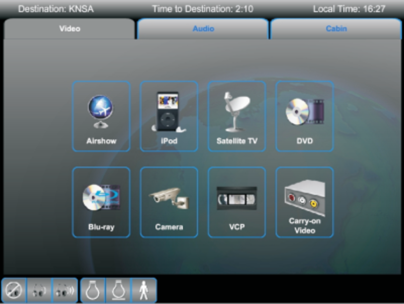
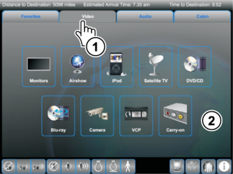
Video Function
Example shown is on a Master Seat Location TSE.
- Touch the VIDEO tab.
- Touch one of the main video selections. The options are: Monitors, Airshow, iPod, Satellite TV, DVD/CD, Blu-ray, Camera, VCP, and Carry-On.
Monitors Selection
- Touch desired monitor(s). System shows available speakers, monitor settings, movie presets, and video sources.
- Touch QUICK SELECT button for quick access to video controls of the source currently playing on the monitor.
- Touch MONITOR LEGEND for the Monitor Location information.
- Touch On-Screen Menu for On-Screen Display Controls.
- Touch desired video source to select for the highlighted monitor(s).

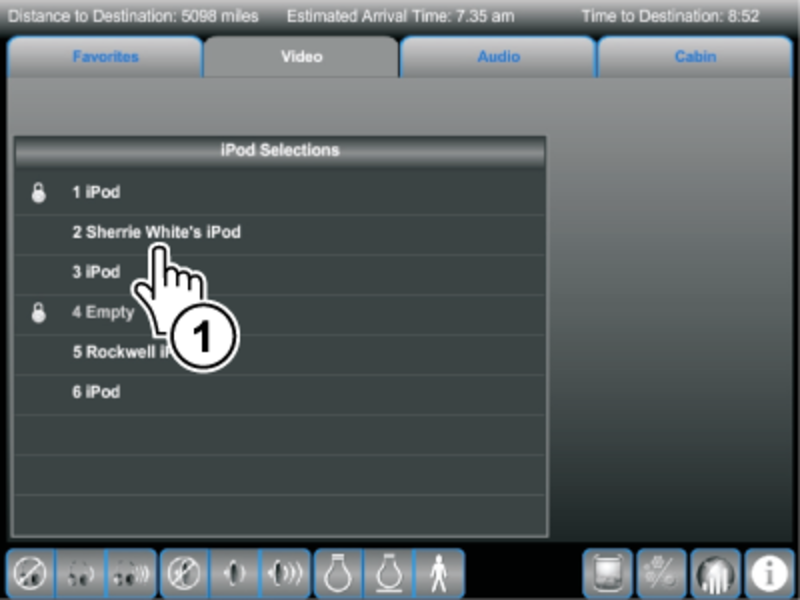
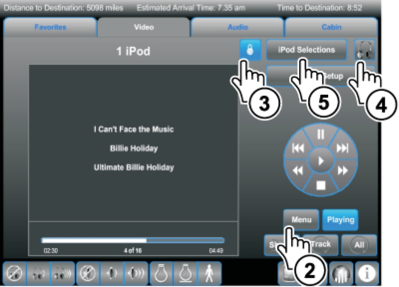
iPod Selection
- Touch one of the iPod selections to watch iPod video or listen to iPod music.
- Touch MENU button to view iPod menu selections.
- Touch source lock button to lock or unlock iPod. Controls for the iPod are only provided to the owner of the lock, preventing other users for interrupting iPod media. The user is notified, when ownership of a lock is lost.
- Touch headphone icon to listen to the selected iPod on the local headphone.
- Touch Cabin Setup button to select monitor(s) and/or speaker(s) to play iPod media.
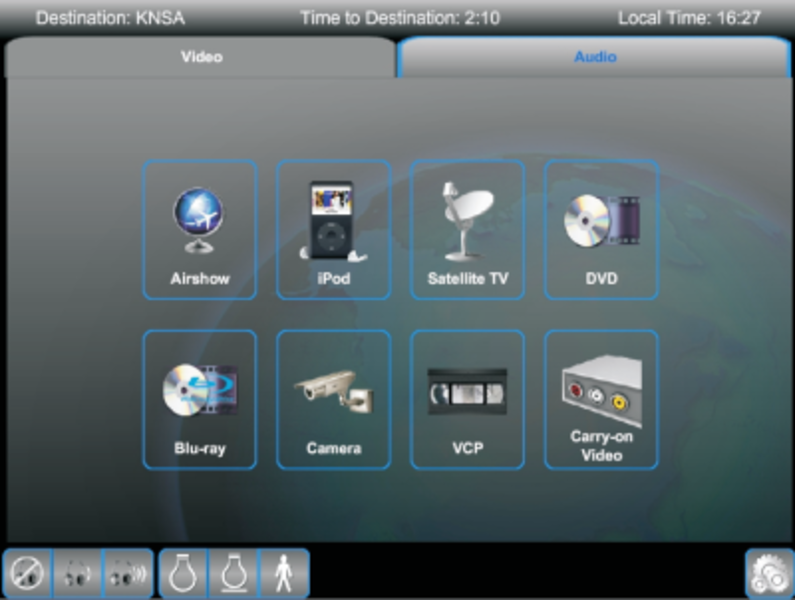
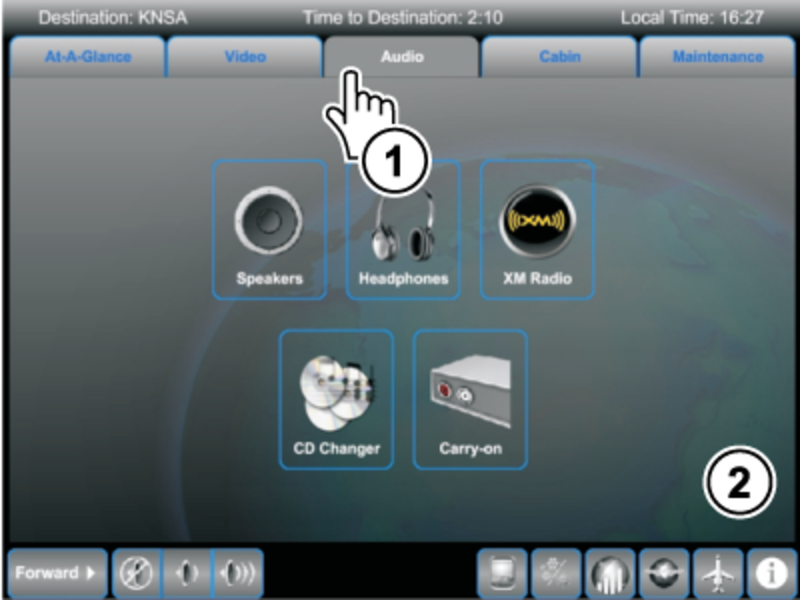
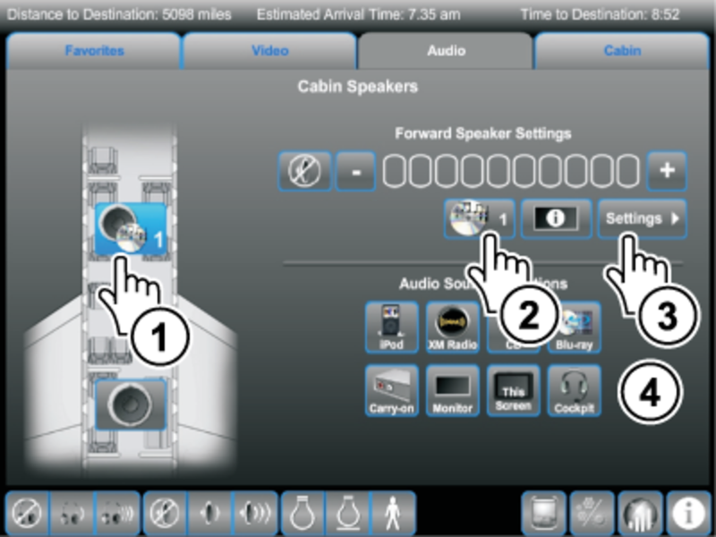
Audio Function
Example shown is on a Galley TSE.
- Touch the AUDIO tab.
- Touch one of the AUDIO icons.
Speakers
- Touch desired speaker(s). System shows available speaker settings, and audio sources.
- Touch Quick Select button for quick access to audio controls of the source currently playing on the speaker.
- Touch Settings to adjust selected speaker settings.
- Touch desired audio source to select for the highlighted speaker(s).
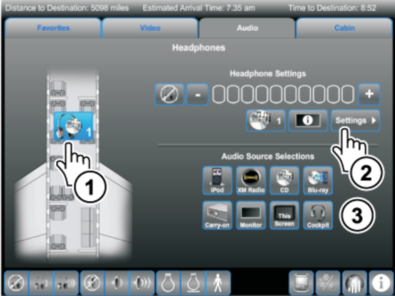
Headphones
- Touch desired headphones. System shows available headphone settings, and audio sources.
- Touch Settings to adjust selected headphones settings.
- Touch desired audio source to select for the highlighted headphones.
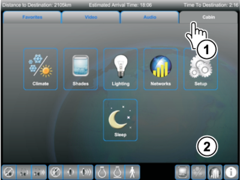
Cabin Function
Master Seat Location TSE
- Touch the CABIN tab.
- Select one of the available choices: Climate, Shades, Lighting, Networks, Setup, or Sleep.
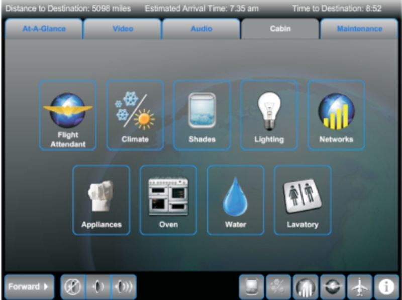
Galley TSE Choices
- Touch the CABIN tab.
- Select one of the available choices: Flight Attendant (Presets, Briefings, Setup, and Cabin Maps), Climate, Shades, Lighting, Networks, Appliances, Oven, Water, or Lavatory.
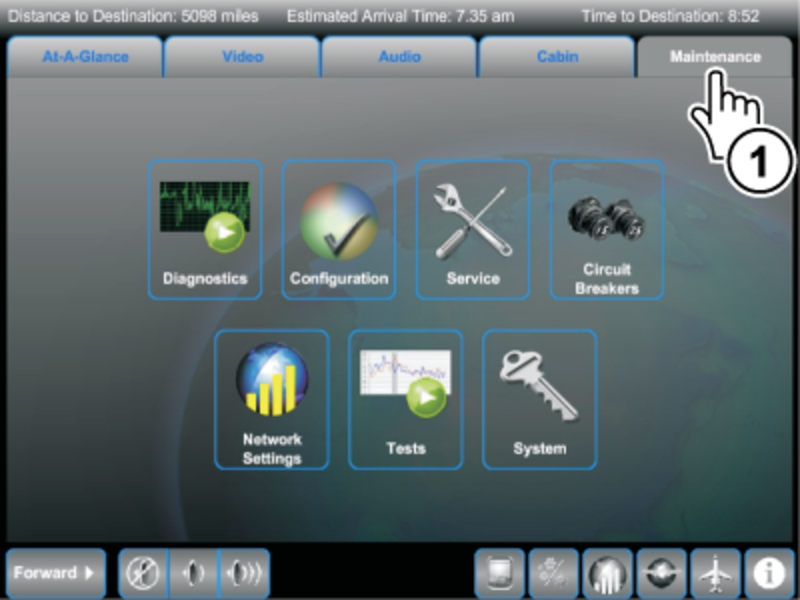
Maintenance Function
Galley TSE
- Touch the MAINTENANCE tab.
- Select one of the available choices: Diagnostics, Configuration, Service, Circuit Breakers, Network Settings, Tests, or System.
Note:
When executing the request for a maintenance category touch screen, and until the requested page shows, the words 'Acquiring Data...' show on the screen (for example Diagnostics, Current Faults).
Diagnostics Icon - Touching the Diagnostics icon shows the Diagnostics page. The Diagnostics screens show detailed maintenance and diagnostic information. Current Faults, Fault History, and Current Status screens are available. They are intended for use by maintenance personnel to evaluate the system, and to diagnose any problems. Information from the diagnostics screens can be printed using the onboard computer.
Configuration Icon - Touching the Configuration icon shows the current software versions.
Service Icon - Touching the Service icon shows necessary maintenance services required for onboard equipment.
Circuit Breakers Icon - Touching the Circuit Breakers icon shows a list of available Air Transport Association (ATA) chapters. The Circuit Breaker list of ATA chapters highlights which category has a tripped CB. The circuit protection screens are not password protected and are intended for use by the cabin crew.
Network Settings Icon - Touching the Network Settings icon shows the (Maintenance category) networks page.
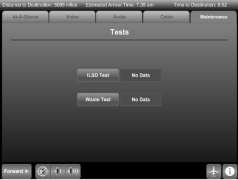
Tests Icon - Touching the Tests icon shows the Tests page. The Tests page shows the Waste Test and ILSD Test buttons. Push the Waste Test button to start the Initiated Built In Test (IBIT) of the waste subsystem. Push the ILSD Test button to start the IBIT of the Interior Lighting System Director (ILSD) subsystem. Test results also show on the Tests page.
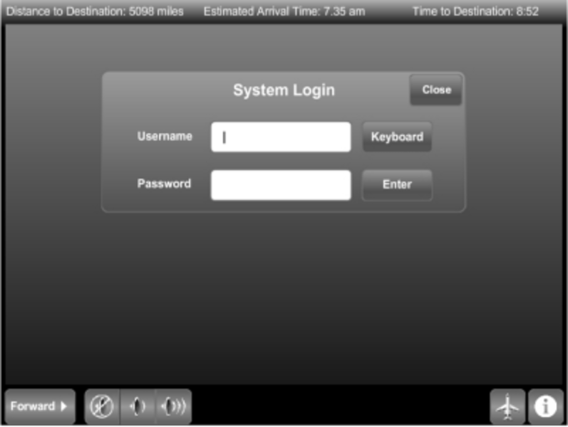
System Icon - Touching the System icon shows the System log-in page. The CES operations and configurations that require the expertise of a maintenance technician are accessed by a password-protected, log-in screen. The password is typed into the password field using the touch screen keyboard. Once a valid user name and password has been entered, the System sub-screens become available. Selecting another content category causes an automatic logout.
Short-Cut Controls
Discussing each, starting from left to right, the following icon buttons show at the bottom of every maintenance page:
Speaker Controls - The icons on the bottom-left control the CES speakers. Touch the left-most button, and the label on the button advances to the next control area. That is, if the button shows Forward (defaulted state, forward control is active). Touch the button, and the label Aft shows (Aft control is active). Touch it again and it shows All (control of all CES speakers is active). Touch it again and the Forward label shows again. Touch the first speaker icon to the right of the Forward-Aft-All button and the speakers in the selected area(s) are muted. Touch the next speaker icon and speaker audio is decreased in the selected area(s). Touch the farthest-to the right speaker icon and speaker audio is increased in the selected area(s).
Shades – Shows the Shades control screen (optional)
Climate – Shows the Climate control screen (optional)
Networks – Shows the Networks control screen (optional)
Flight Attendant – Shows the Flight Attendant screen in the Cabin section (optional)
Call Lights Map – Shows the cabin Call Light Seat Location Map control screen
Message Center – Shows the Message Center screen.
Diagnostics
Built-in system diagnostics monitor the reporting LRUs in the CES. The diagnostics show both dynamic status reports and recorded fault history logs. The following paragraphs describe the various diagnostic functions. Use these diagnostics to test and troubleshoot the Cabin Electronics System. The technician should become familiar with the capabilities of the diagnostic system before starting the LRU fault isolation procedures provided later in this manual. The Galley TSE serves as the main CES built-in test and diagnostic interface.
The Diagnostics page provides more detailed information from the central maintenance and diagnostic function. These screens are intended for use by maintenance personnel to evaluate the system and diagnose any problems. The Diagnostics screen has the buttons to show the screens and sub-screens that follow (default is Current Faults page):

Current Faults - Current Faults screen shows a list of currently non-functioning LRUs. These data fields show the names of each malfunctioning unit, the LRU status message, and the diagnosed fault message. The LRU field names the unit that is currently diagnosed as nonfunctional. Each unit is a probable failed LRU, but look at the status field before taking any action.
The Failed condition means that the diagnostics suspect a LRU failure; replace this LRU with a known good unit. The Failed/Wiring condition means that the diagnostics suspect a LRU or wiring failure; test the wiring before replacing this LRU. The Off/No Output condition means that no diagnostic words are received from that LRU; make sure that power is input to the unit before taking further action. The Overheat condition means that a LRU is overheating; make sure the fan/cooling system for that unit is operating. The LRU OK/Info condition means the LRU is good and the message shows on the diagnostic page to record an event. The Deferred Maint condition means the LRU is good, but maintenance, for example replacing a low battery, will soon be required. The Maintenance condition means the LRU requires maintenance.
On the Current Faults page, move the highlight line to the desired LRU and push the Details button to show the Details page. The Details page provides the variable of the logic equation that is used to generate the fault message.
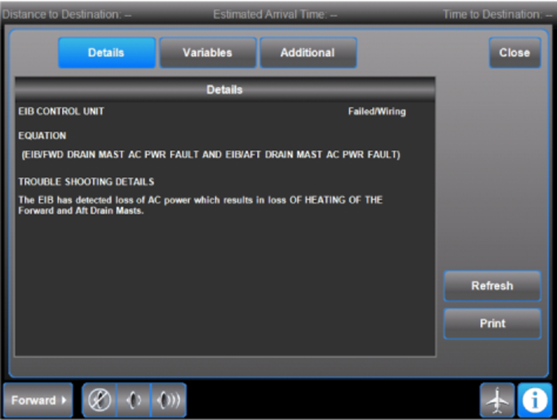
A Variables sub-page provides specific information on the variables of the fault equation.
Each of the variables of the fault equation are listed with the Comparator, Operator, and Value. The operator Not Equal indicates that the variable will become active when the value shown is not equal to the comparator. Thus a value of '1', being not equal to the comparator '0', activates the comparator.
In the example shown, as indicated by the word 'AND', both variables must be active to complete the fault equation. Since both variables are active, the fault message is displayed.
The Additional sub-page in some cases provides additional information.


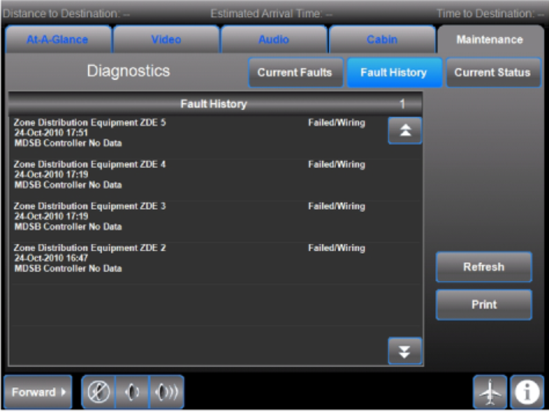
Fault History - The Fault History page shows a list of the LRU fault entries that have been shown on the Current Faults page. The LRU fault entries show when a fault is diagnosed.
A record of when faults occur is stored in the processor/mass storage equipment (PME) memory.
This Fault History page presents a list of faults with component name, date and time and the type of fault detected. This information is provided as history only. No action is required on the basis of this information alone.
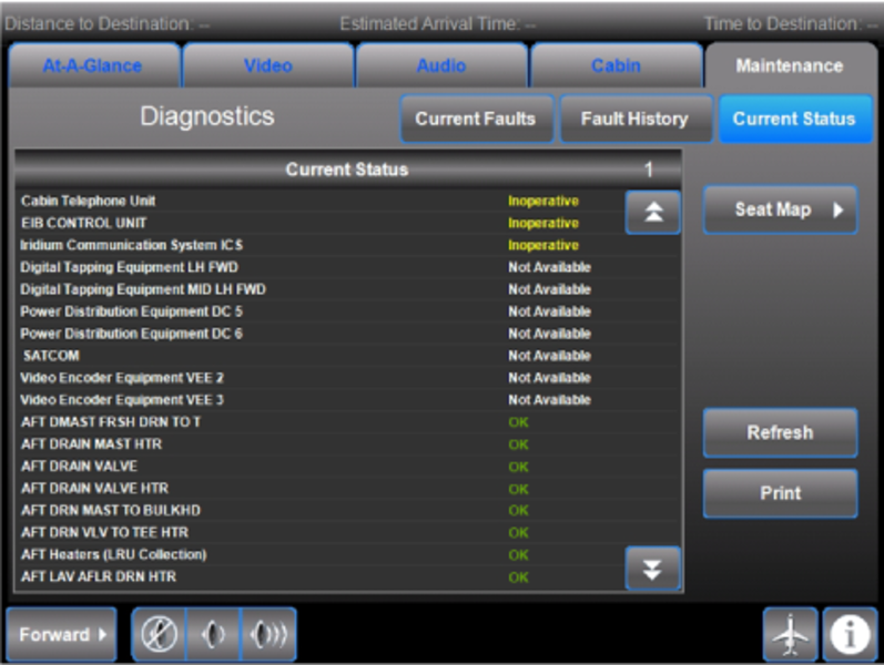
Current Status - The Current Status page shows the status (for example OK, Inoperative, Not Available) of each LRU or subsystem.
Units that report Inoperative can be further investigated on the Galley TSE.
Units that report Not Available should be verified that they are receiving power.
The page can be Refreshed to ensure that the latest system status is being displayed.
A Seat Map is provided for reference.
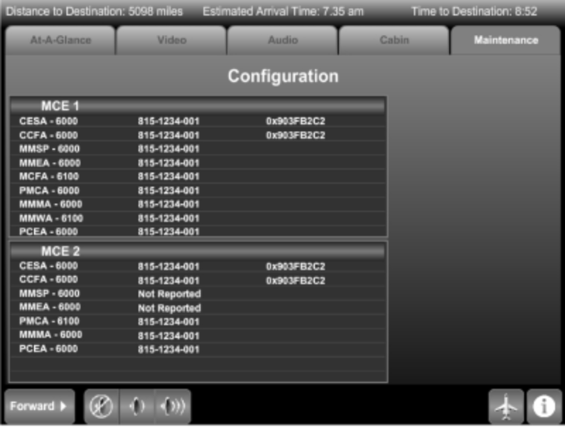
Configuration
The Configuration page shows the application software file names, the part numbers and a Cyclic Redundancy Code (CRC).
For the purpose of troubleshooting, ensure that the part numbers for the PME software, CESA-6000, and the configuration database file CCFA-6000 match between MCE 1 and MCE 2. Also verify that the CRC codes match. If they do not, software has not been loaded properly or is corrupted, and must be reloaded.
Corrupted software can cause the CES to act differently with each reboot of the system or some integrated systems to experience issues.

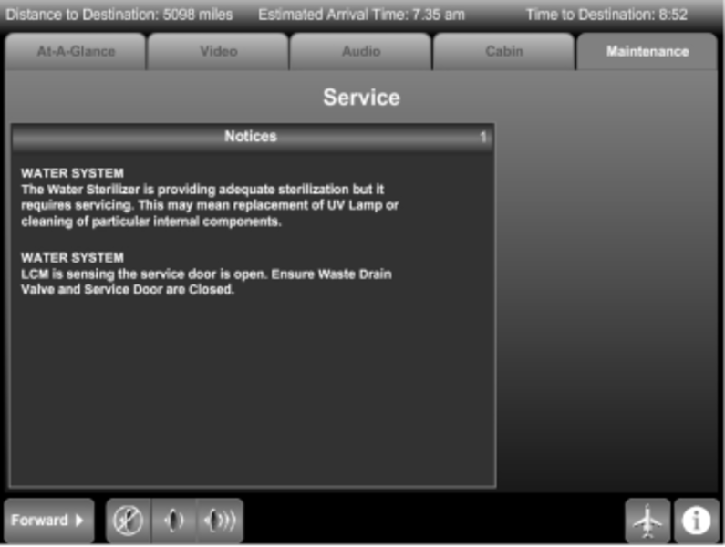
Service
The Service page shows notices about the LRUs that require service. The kind of service required for an LRU shows below the LRU name. After the maintenance is complete, the message is automatically removed. Push the page up/down buttons to show the previous or next page. (The paging is only shown when there is another page before or after the page being displayed.) Page number shows on Notices line.

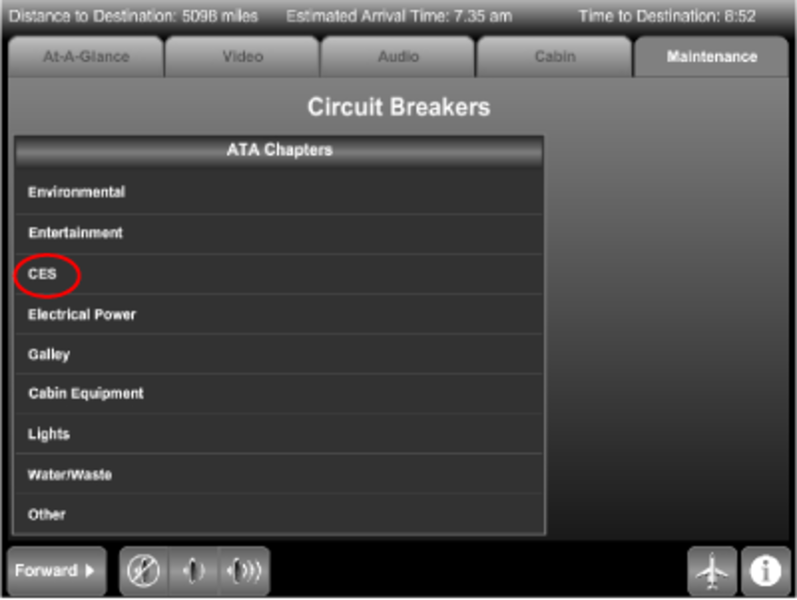
Circuit Breakers
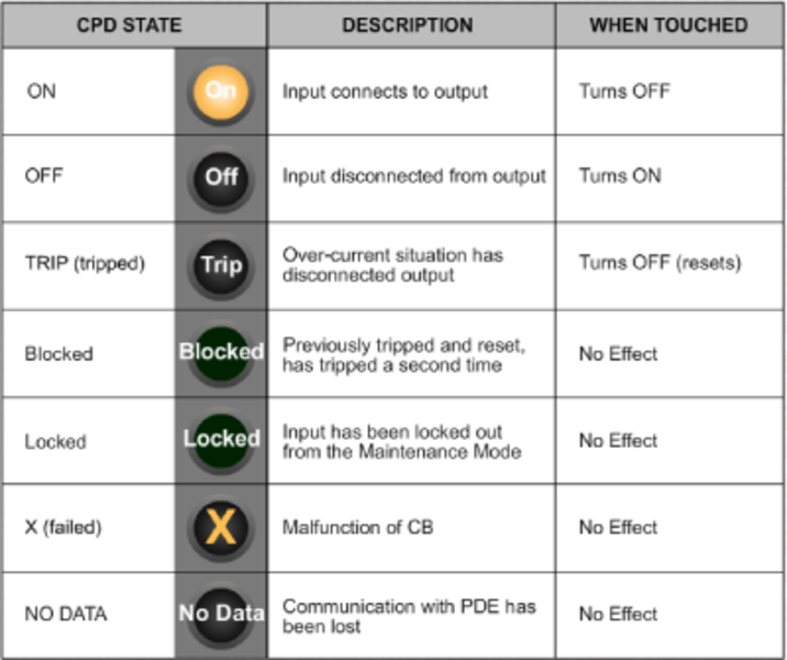
The Circuit Breakers page gives access to the Circuit Protection Devices (CPD). The CPDs are physically part of the AC and DC Power Distribution Equipment (PDE). The CPDs are grouped under an ATA menu category to provide ease of navigation. The menu category line lights to show which category has a tripped CPD. The circuit breaker screens are not password protected, and are intended for use by the cabin crew.
The possible circuit breaker conditions exist as follows:
- CPD shows On. The CPD is turned on, such that its input is connected to its output. Push the CPD again to turn it Off
- CPD shows Off. The CPD is turned off such that its input is disconnected from its output. Push the CPD again to turn it On
- CPD shows Trip. The CPD output is disconnected from its input due to an overcurrent condition. The CPD has to be reset before it can be turned On again. Push the CPD to command a reset and turn it Off
- CPD shows Blocked. The CPD has previously tripped once and has been reset and tripped a second time in flight. Touching the CPD again has no effect
- CPD shows Locked. The CPD output is disconnected from its input and the CPD can not be turned On without first being unlocked in Maintenance System. Touching the CPD has no effect
- CPD shows X. The CPD is not functioning properly. Touching the CPD has no effect


Network Settings
The Network Settings page covers the subjects that follow:
- Equipment Status - of printer,WLU, etc. To control the wireless connection, for example, push the On/Off button under the label Wireless Connection on the left hand side of the page
- Internet Connection (On button optional) or Wireless Connection
- Login Settings button - Touch this button and the Login Settings page shows
- HST History button - Touch this button to show the HST Status History page
The Internet Connection controls functions of the Off-Aircraft Communication section includes the Suspend SATCOM feature, when configured. Push the SUSPEND SATCOM button to disable the Iridium communications and remove possible interference with SATCOM Off-Aircraft Communications.
To accomplish login, do the following.
- On the Network Settings page, push the Login Settings button. Login Settings page shows. When only the Swift 64 is available, the Login Settings shows as Swift 64 Login Settings.
- On the Login Settings page, Push the KEYBOARD button. Keyboard shows below the Login Settings page. Push the keyboard
CAPS LOCK key to toggle between the upper and lower case letters. The number keys show with the lower-case alphabet keys. - Type in the following information, After each entry in a data entry field, push the Save button.
Note:
The following steps (d) through (f) are not always options. It depends on the CES features that the aircraft has. If the aircraft only has Swift64 with one HST, SwiftBroadband, or the Swift64 Low Speed button is selected, only item (e) shows. If the aircraft has two HSTs, items (d) through (f) show.
(a) User Name.
(b) Password.
(c) Service Name Dial Up Number.
(d) HST2 Activation Threshold (percent of HST1 Activation) Keypad shows. On the keypad push in percent of HST1 activation time (for HST2 use, Swift64 High Speed).
(e) HST1 Timeout 0-30 Minutes (Disconnect after Timeout). Number of minutes of use before HST1 disconnect. Push 0 on the keypad for no disconnect.
(f) HST2 Timeout 0-30 Minutes (Disconnect after Timeout) (Swift64 High Speed). Number of minutes of use before HST1 disconnect. Push 0 on the keypad for no disconnect.


Tests
The Tests page shows the Waste System and ILSD System test buttons. Push the Waste System button to start the Initiated Built In Test (IBIT) of the waste subsystem. Push the ILSD SYSTEM button to start the IBIT of the Interior Lighting System Director (ILSD) subsystem. The test readout window shows the self test progress for both ILSD and Waste tests. The progress message shows Running, Pass, Fail, or No Data.

System
The CES operations and configurations that require the expertise of a maintenance technician or Rockwell Collins service center personnel are accessed by a password-protected login screen. Selecting a content category outside of System causes an automatic log-out. To get to the System menu, do the following.
- Push the Maintenance tab. Maintenance menu shows.
- On the maintenance menu, push the System icon. System Login shows.
- On the System Login page, push the keyboard button. Keyboard shows.
- Enter data into the following:
(a) Username
(b) Password (123456)
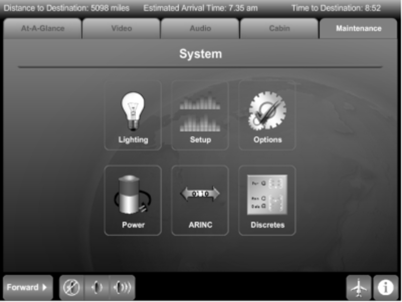
- Push the ENTER button. System Menu shows the following icons:
- Lighting
- Setup
- Options
- Power
- ARINC
- Discretes

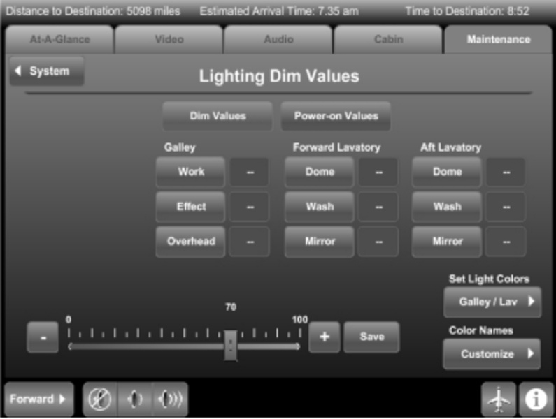
Lighting - From the System menu, to use System Lighting, do the following:
- Push the Lighting icon. Lighting Dim Values page shows with Dim Values button lit.
(a) Set Dim Value - Push the desired Cabin, Galley, Forward and/or Aft Lavatory light button. (This can be done individually, plurally, or all together).
(b) To adjust the lighting to the selected area (for example Galley, Overhead), click on the adjustment bar on the measurement value line, and move the bar to the desired level of lighting (to the left or - to decrease, and to the right or + to increase). The number above the adjustment bar represents the level of adjustment.
(c) Push the SAVE button to save the dim value setting(s) for the selected lights. The set value is displayed in the readout next to the button. If no value is set, then -- (dashes) are shown.
- If Lighting Power-on Values is needed, push the Power-on Values button. Lighting Power-on Values page shows.
(a) Set Power On Value - To change the Power ON value of a light, push the desired light button(s). (This can be done individually, plurally, or all together).
(b) To increase or decrease the power on value, click on the adjustment bar on the measurement value line, and move the bar to the desired level of lighting (to the left or - to decrease, and to the right or + to increase). The number above the adjustment bar represents the voltage level selected.
(c) Push the Save button to save the power on value setting for selected lights. The set value is displayed in the readout next to the button. If no value is set, then -- (dashes) are shown.

- From either Lighting Dim or Power-on Values page, to set Colors for Galley and Lavatory Wash Lights, do the following:
(a) To change the color of the Galley and Lavatory wash lights, push the Set Light Colors GALLEY/LAV button. Color pop-up shows with the available color options.
(b) Push the desired color button. The button lights up.
(c) To go back to either the Lighting Dim or Power-on Values page (from which Galley/Lav button was touched), push the Close button.

(d) From either Lighting Dim or Power-on Values page, to change color names, push the Color Names Customize button. Change Color Names page shows.
(e) Click in the window where the color name is to be changed. Keyboard shows below the color name readouts.
(f) Type the name using the on-screen keyboard.
(g) To save the color name changes, push the SAVE button.
(h) To go back to either the Lighting Dim or Power-on Values page (from which Galley/Lav button was touched), push the CLOSE button.

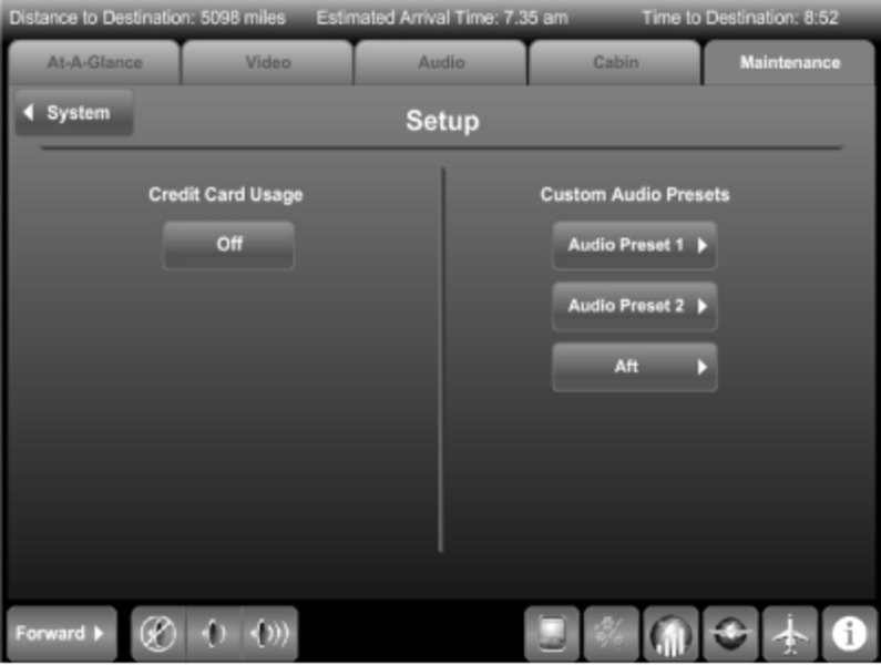
Setup
Credit Card - Push the Credit Card Usage ON/OFF button to toggle between enabling and disabling the credit card function of the telephone system.
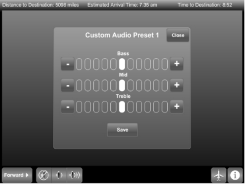
Customize Presets - To customize audio presets, do the following:
- Push the desired Audio Preset 1 or 2 button. Custom Audio Preset page shows.
- Push one of the eleven the Bass-level buttons to raise (+) or lower (-) base audio to the desired speaker level.
- Push one of the eleven Mid-level buttons to raise or lower the mid level audio to the desired speaker level.
- Push one of the eleven Treble-level button to raise or lower Treble-level audio to the desired speaker level.
- When the desired mix of audio is reached, push the SAVE button.
- When the Custom Audio Preset Screen is no longer needed, push the CLOSE button. Setup screen shows.
- When Setup is no longer needed, push the SYSTEM button. System Menu screen shows.
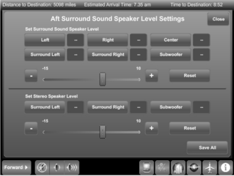
- If the aircraft is equipped with forward or aft Surround Sound, push the related Forward or Aft button. A different pop-up is displayed allowing control of all surround sound settings for the specified (forward or aft) audio zone.
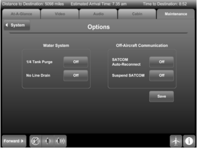
Options - To activate the Options page, do the following:
- From the System menu, push the Options icon. Options page shows (All On-Off buttons are deferred to Off).
- To turn the Water System 1/4 Tank Purge and/or No Line Drain, or to turn Off-Aircraft Communication On or Off, push the respective ON/OFF button(s).
- To turn Off-Aircraft Communication activities on or off, push the On/Off buttons to the right of SATCOM Auto-Reconnect and/or Suspend SATCOM.
- Push the Save button to save either Off-Aircraft Communication or Water System settings.
- Push the System button to return to the System menu.
Power - The system DC and AC PDE screens (AC is shown as typical of both AC and DC) provide access to the configuration and maintenance functions of the Power Distribution Equipment (PDE). Depending on the mode that the PDE is in, controls may be enabled or disabled. The Maintenance Enable switch in the flight deck must be set and the aircraft must have weight-on-wheels to enable all the controls (Maintenance Mode). The PDE pages show the PDE modes. The possible PDE modes are as follows:
- NEW INSTALL
- NORMAL
- MAINTENANCE
- NEW INSTALL/MAINT
- NO LRUDATA
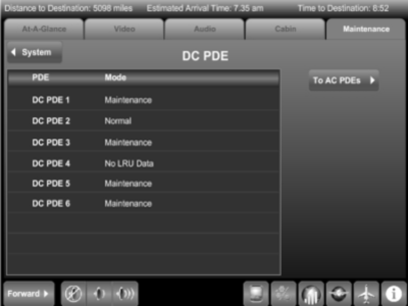
To operate System Power, do the following:
- On the System menu page, push the Power icon. The screen defaults to showing the DC PDE page. (Since both AC and DC power is operated identically, only AC is described).
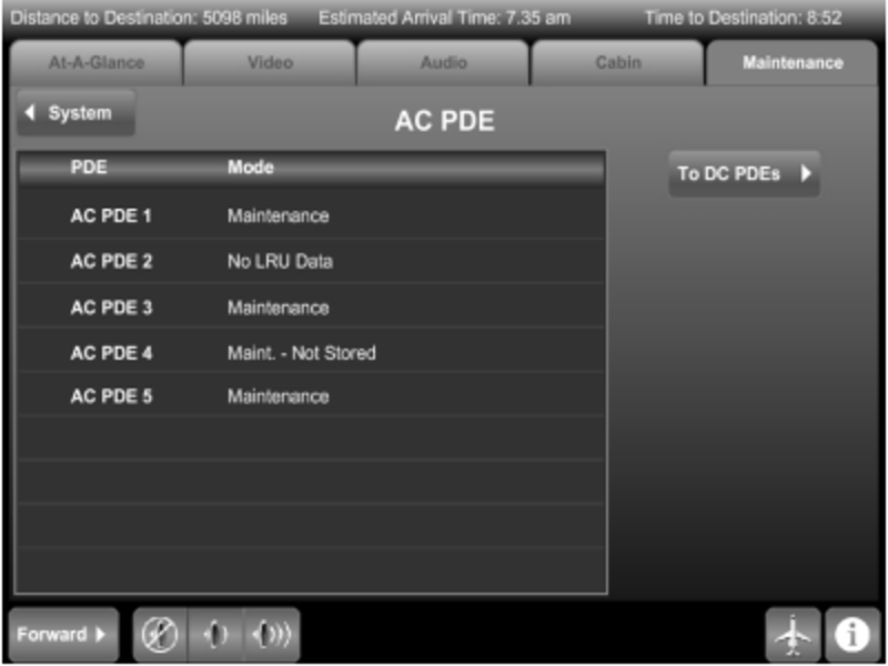
- On the DC PDE page, push the To AC PDEs button. AC PDE page shows. (While on the AC PDE page, to go back to the DC PDE page, push the To DC PDEs button).
- To go to a PDE page, on the AC PDE page, push the line showing the desired PDE (for example, AC PDE 4, defaults to the current condition).
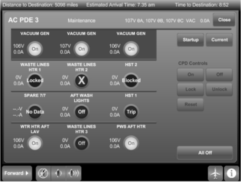
The Circuit Protection Devices (CPD) are part of the PDEs and have the functionality of a circuit breaker. The CPD can be reset only once per flight. Some AC CPDs are grouped together with the same name (for example, VACUUM GEN). CPDs that are ganged together are surrounded by a darkened background on the PDE screen.
The PDE Current status page shows the Current status for all CPDs on the selected PDE. The possible CPD states are as follows:
- On - CPD is turned on, such that its input is connected to its output.
- Off- CPD is turned off, such that its input is disconnected from its output.
- Locked - CPD output is disconnected from its input and the CPD can not be turned ON without first being UNLOCKED in Maintenance System.
- Blocked - CPD has tripped, has been reset, and tripped a second time in flight.
- Trip (Tripped) - CPD output is disconnected from its input due to an over-current condition. The CPD must be RESET before it can be turned ON again.
- X (Failed) - CPD has failed. The CPD is either inoperative or something in the CPD output has failed. The Current status page includes controls to change the state of the selected CPD.
To operate the Current status CPD Controls, do the following:
- Push the desired CPD to select it.
- Push the On button to set the selected CPD to on. The CPD changes state only if previously Off. If the selected CPD is ganged with other CPDs, all ganged CPDs show on.
- Push the Off button to set the selected CPD to Off. The CPD changes state only if previously on or tripped.
- Push the Lock button to command the selected CPD to be locked. The CPD is off when locked. The CPD does not change state, unless it previously showed On, Tripped, Off, or Blocked.
- Push the Unlock button to set the selected CPD to unlock. The CPD shows Off and the reset counter is set to 0. CPD changes state only if previously locked.
- Push the Reset button to reset a Tripped or Blocked CPD to Off Status. The reset counter is set to 0. The CPD only changes state if previously tripped or blocked.
- Push the All Off button to turn off all the CPDs on the PDE Current status page.
- Push the Startup button to show the related PDE Startup page.
- To return to the AC (or DC) PDE page, push the Close button on the selected PDE page.
- To return to the System menu, push the System button.
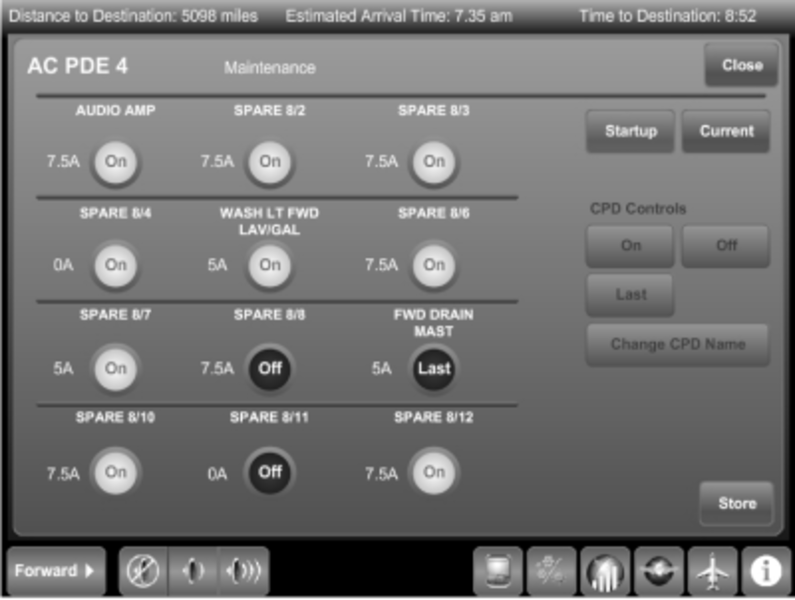
The PDE Startup page shows the initial startup state for all CPDs on the selected PDE. The starter CPDs cannot have their power-up setting changed. The possible initial CPD states are as follows:
- ON
- OFF
- LAST
The Startup page includes controls to change the state of the selected CPD and the name to which the system defaults. The CPD Controls section of the Startup page is as follows:
- ON
- OFF
- LAST
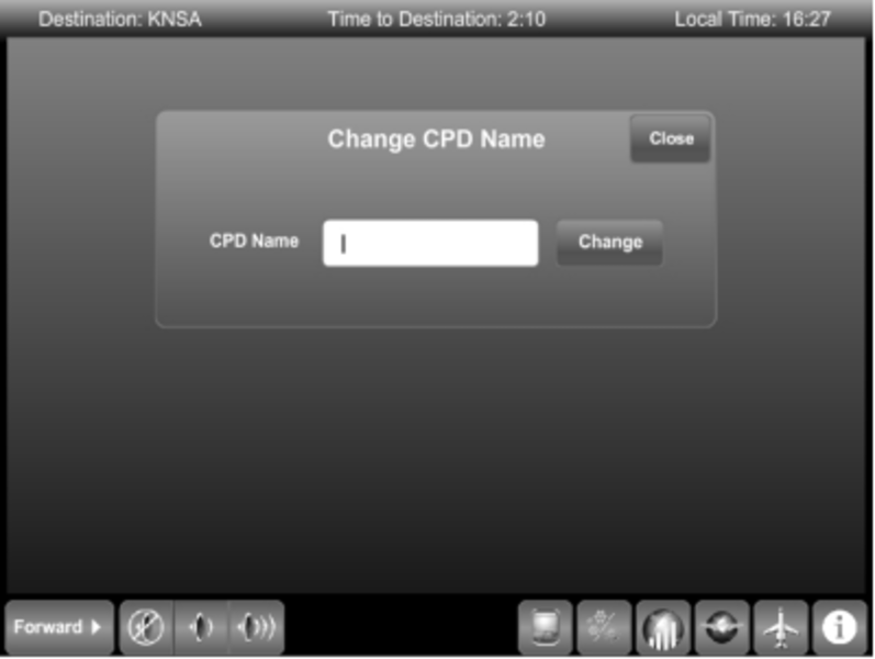
- Change CPD Name
The ability to change the CPD name is an option. The CPD trip rating shows to the left of the CPDs. The possible trip ratings are as follows:
- OFF
- 2.5A
- 3.75A
- 5A
- 7.5A
- 10A
- 15A
- INVLD (Invalid Setting)
To operate the Startup CPD Controls, do the following:
- Push the desired CPD to select it.
- Push the On button to set the selected CPD Startup state to on. The CPD changes state only if previously off or last. If the selected CPD is ganged with other CPDs, all ganged CPDs show on. All CPDs showing the On state will be turned on at startup.
- Push the Off button to set the selected CPD Startup state to off. The CPD changes state only if previously on or last. All CPDs showing the Off state will remain off at startup.
- Push the Last button to set the selected CPD Startup state to Last. All CPDs showing the Last state will be the last to be turned on at startup.
- To change the CPD Name, push the CPD Name button. Change CPD Name screen shows with the following label and control buttons:
- CPD Name (type-in window)
- Change
- Close
- Click in the window where the CPD Name is to be changed. Keyboard shows below.
- Type in the selected new name using the on-screen keyboard.
- To save the new name, push the CHANGE button.
- To exit the Change CPD Name screen, push the CLOSE button. The Startup CPD screen shows.
- Push the STORE button to save the CPD startup settings that show on the display.
- Push the CURRENT button to show the related PDE Current status page.
- To return to the AC (or DC) PDE page, push the Close button on the selected PDE page.
- To return to the System menu, push the SYSTEM button.
ARINC 429 Bus Status - The ARINC 429 Bus Status page allows the maintenance personnel to see the ARINC 429 input/output activity in the Modular Cabinet Equipment (MCE).The ARINC 429 Bus Status shows the number of words received on the six ARINC 429 inputs and the number of words transmitted on the six ARINC 429 outputs. To activate the ARINC 739 Emulator, push the ARINC 739 Emulator button.


ARINC 739 Emulator Page
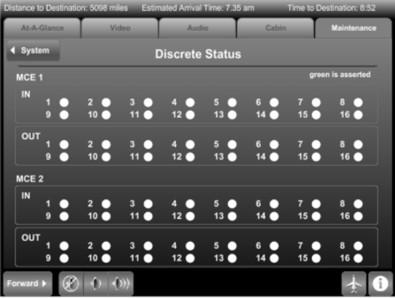
Discrete Status - The Discrete Status page allows the maintenance personnel to see the discrete input/output activity in the MCE. The Discrete Status shows the status of the 16 discrete inputs and the 16 discrete outputs. A Discrete Status shows green when that discrete is asserted.
System Interface
MCE-6000 Modular Cabinet Equipment Interface

ZDE-6000 Zone Distribution Equipment Interface
A ZDE is the primary interface distribution node for a particular seating zone area. The ZDEs provide the different seating zone connectivity configurations.
Power Distribution
Power for much of the cabin area is provided by PDEs. Each PDE provides circuit protection and also allows for individual system power to be turned off or on. The CES backbone equipment interfaces with the PDE to allow for limited control of individual system power, limited circuit protection resets, and monitoring functions. The PDE is intended to provide a modular approach to distributing power throughout the aircraft cabin. The PDE provides a sufficient number of independently protected circuits to provide power for any equipment likely to be installed in a particular zone of the aircraft. The ZDE outputs an RS-485 bus that connects the PDE to the network.
System Software
CES Software
The core software for the CES resides in the PME. The operating system is Linux. Multiple software applications define the range of the PME functionalities. These include the master/slave application and the control and display application.
The master/slave application is responsible for starting all the other applications in the PME and to determine which PME is master and which is slave. The control and display application provides the interface to the Galley TSE and passenger TSEs. Inputs from the TSEs are processed and communicated over to end-devices.
The maintenance application is responsible for processing maintenance message information from the CES as well as from the water system, lighting system, and PDEs, etc. It is also responsible for posting the maintenance status for display on the Galley TSE maintenance page.
The Multi-Drop Serial Bus (MDSB) data loader application checks if the software version on the MDSB controllers in the ZDEs are different, and if different, the new software is uploaded.
The ARINC/discrete application provides I/O functionality for these types of signals.
The web server/TFTP server stores the GUI, (e.g. ver 7.1), and transfers the applicable software and configuration files to end-devices, on boot up, whenever a new version is available. If the receiving unit does not store its software in NVM, upload occurs automatically on every power-up. For example, on power-up, the Galley TSE must reload its GUI.
The tunneled application provides communication to all end-devices that are connected to a serial bus.
Configuration files are XML files that capture the specific configuration of the aircraft. The aircraft configuration file is loaded into the configuration database in the PME, and contains configuration information for:
- Circuit breaker (CPD) mapping
- Presets of cabin lighting
- Temperature display
- Audio presets
- Moving map options
- End-device options and connectivity
- Other configuration information
The software part numbers can be viewed on the Galley TSE under the Maintenance tab ant the Configuration icon.
Since every aircraft is unique, the configuration file can only be used on one aircraft. The file name is CCFA-6000. The part number is 810-0035-9364B, where '9364' is the aircraft serial number. 'B' indicates the revision status.
The alphanumeric code at the far right is the cyclic redundancy check (CRC) used to verify successful installation of the file.


Software Loading
Software for the CES is loaded into the PME using Rockwell Collins CPAS-3000 application installed on the maintenance laptop.
Files for the airshow network and passenger briefings are loaded via FTP transfer into the MME. CES files are first loaded into the PME after which the PME must be rebooted. Upon reboot, the CES LRUs are also rebooted with the new version of their software.
After loading, the Galley TSE is reviewed to see if the files have been loaded correct.
The installed software part numbers can be verified on the Configuration page described above.
The table below provides more information on CES software including a description, the installation location, and the relevant codes. Some of the software versions currently in use are listed. The software part numbers, with the corresponding dash numbers, are provided for each equipment type.
Note:
The High definition passenger Touch Screen Equipment (HTSE) requires Version 8.0 software.


System Monitoring
PME ARINC 429 Traffic Monitoring
The Galley TSE provides a means of monitoring the traffic in ARINC words. This utility verifies that communication is taking place between the PME and the corresponding unit. The table below identifies the units that the PME communicates with. For example, PME 1 in MCE 1 receives ARINC 429 words from FMS 1 (for airshow) on MCE 1, input 3. On the Galley TSE ARINC 429 Bus Status page example below show that since power-up, over 1,800,000 words have been received. A display of '0' indicates that either no unit is connected, the assigned unit is unpowered, or there is a communication fault. Dashes in the table indicate no connection.
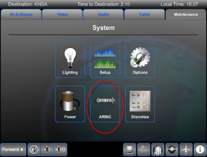


PME Discrete Signal Monitoring
PME discrete inputs can be monitored on the Galley TSE. On the Discretes Status page green lamp(s) illuminate if the signal is assertive (active). In the illustration below, the Iridium comm system provides an input on MCE 1, input 3.
Green lamps do not always indicate normal or serviceable conditions, such as Iridium channel available.
The table below shows the monitored MCE discrete inputs and outputs.
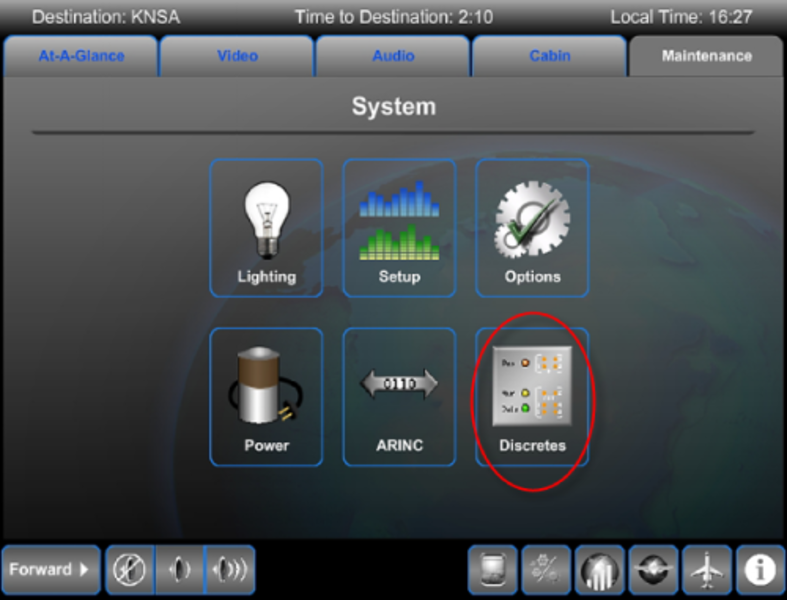


09/24/20
Component Location Index
| Component Location Index | |||
|---|---|---|---|
| IDENT | DESCRIPTION | LOCATION | IPC REF |
| A515/A516/A517/A518 | RELAY DRIVE EQUIPMENT | ZONE(S) 141/231/171 | 44-10-40 [ GX ] [ GXRS ] [ G5000 ] |
| ZONE(S) 232/241/242 | 44-10-40 [ GX ] [ GXRS ] [ G5000 ] | ||
| - | ETHERNET SWITCHING EQUIPMENT MODULE | ZONE(S) 232 | 44-10-55 [ GX ] [ GXRS ] [ G5000 ] |
| A578 | WIRELESS LAN UNIT | ZONE(S) 231 | 44-10-69 [ GX ] [ GXRS ] [ G5000 ] |