


05/19/16
Overview
The primary function of the passenger entertainment system is to give the passengers quality audio and video entertainment. In addition to the primary function, the system also give the provisions for carry-on items, such as gaming devices. The passengers hear the audio signal from the cabin speakers or from the local headphones. The passengers see the video signal from the bulkhead monitors, the galley or the passenger seat touchscreens.
The entertainment system is controlled by a system which consists of controllers, a centralized processing center, distributors, and receivers, which is referred as:
- Cabin Electronic System
The entertainment system is operated from the touchscreens, the passenger control units and directly from the source equipment. The passenger entertainment system is integrated with the cabin electronics system (CES). The CES uses an Ethernet-based local area network (LAN) as the backbone for the cabin system communication. This includes the audio and video signal, global office functionality and the aircraft-cabin systems management.
The entertainment system has interfaces with:
- Security System
The CES provides an integrated passenger entertainment system. This system is capable of reproducing CD quality audio and DVD quality video in the cabin. The audio and video content is distributed digitally throughout the cabin. The digital encoded content is decoded at each seat location. The entertainment system is controlled by CES system which is responsible for the control, display, and maintenance of the cabin systems and is comprised of the subsystems or functions that follow:
- Source equipment (DVD players, CD players, etc.)
- MPEG encoders (Video Encoder Equipment (VEE))
- MPEG decoders (Digital Tapping Equipment (DTE))
- Personal Monitors
- Cabin Monitors
- Galley TSE
- Audio Video On Demand (AVOD)
- Distribution Network
- Control Devices
- Camera System
- Moving Map
- Carry-on Game Devices (interface only)
- Satellite TV
- Audio Amplifier
- Satellite Speakers
- Sub-Woofers
Note that the system configuration described herein is of a typical aircraft installation and may not reflect your installed aircraft options.
Equipment shown boxed in red are optional for Global 5000, and standard equipment for Global XRS.

05/19/16
Audio System
The audio system includes the equipment that follows:
- Multi-Disk CD Players
- Audio On Demand (AOD) Server
- Laptops
- Carry-On Games
- Carry-On Audio Video Devices
The audio system is capable of reproducing CD high quality sound in two independent areas of the cabin, with provisions for a third. Audio content is distributed in a digital format through the common data bus and decoded at each personal listening location. The video system is capable of reproducing DVD quality video in the cabin. The audio system and the video system consists of source equipment, encoders, distribution equipments, decoders, and destination equipment. The destination equipment includes seat headphones and external amplifiers for cabin speakers. The stereo-analog-output from the multi-disk CD player is encoded by VEE into a Pulse Code Modulator (PCM) stream/channel and multicast onto the Ethernet LAN. The passengers, using the TSE or PCU controls, can select and listen to any of these channels on their headphones. The passenger ZDE decodes the audio for the selected stream and drives the headphones or cabin amplifier. Users of the Galley TSE can select any of these channels to be broadcast to any or all of the cabin speakers. The ZDE connected to the cabin amplifier decodes the selected stream and drives the correct amplifier channel for the selected speakers. The audio system supports up to 24 independent audio channels. The entertainment audio channels (video and audio) are muted when the PA, VA, passenger briefing, or oxygen system is activated.
An optional AOD server resides on the MME file server. The AOD digital output (MP3) is streamed onto the Ethernet LAN through the ESE switch. Each user can access any of the AOD selections through the TSE controls. The pre-recorded briefing content can be multi-casted to cabin and galley/lavatory speakers. The audio system supports up to 24 independent channels of CD quality AOD. The AOD provides a high-speed port for content loading. The carry-on PED, such as game boxes, or portable audio devices (for example, CD Players or MP3 Players), can have their stereo analog outputs encoded into a PCM audio stream by connecting to the game port or VEE boxes. The ZDE decodes the audio stream and drives the seat headphone. In order to avoid audio/video synchronization problems, all audio content of all MPEG-1, 2 encoded video stream is simultaneously decoded by the destination equipment (TSE and Bulkhead/DTE) circuitry. The resulting analog audio signal is then PCM re-encoded and put back onto the Ethernet LAN for transmission to the designated ZDE. The ZDE decodes the audio and drives the appropriate headphone and/or cabin speaker amplifier(s).
The audio controls provided at these devices include:
- On/off
- Speaker mute
- Audio Source selection
- Volume
- Balance
- Equalizer adjustment

Cabin Audio Distribution
The cabin audio distribution system consists of an audio amplifier which drives sub-woofers, mid-range speakers, and tweeters.The audio amplifier is a 4Ω units. It is powered by the ACPDE 4. The audio content from the entertainment source equipment is fed to the ZDE which conveys the audio content to the audio amplifier. The amplifier amplifies the content and sends the ouput to the cabin speakers.
The audio amplifier is a six-channel unit that provides outputs to the speakers in the cabin.
- Four channels at 60 watts per channel drive 10 mid-range/tweeters speakers
- Two channels at 100 watts per channel drive 4 sub-woofer speakers
The speakers are configured as two or three zones with internal crossovers.


10/14/21
Video System
- Source Equipment
- Video Encoding Equipment
- Digital Tapping Equipment
- Decoders
- Moving Map
- Carry-On Games
- Satellite TV (Optional)
- Airshow System
- XM Satellite Radio System (Optional)
- iPod/iPhone Carry-On Connection
- Blu-Ray Player (Optional)
The video system architecture is similar to that of the audio system and consists of source equipment, encoders, distribution, decoders and destination equipment. Destination equipment includes Bulkhead Monitors, Galley TSE, passenger TSEs, and the EFB. Thesource equipment includes the equipment that follows:
- Multi-region DVD players
- Multi-standard VCPs
- Cameras
- Video Address (VA)
- Video On Demand (VOD) Server
- Laptops
- Portable Video Devices
- iPods®
- Blu-ray™ Player
The destination equipment includes the large bulkhead monitors, seat TSE and Galley TSE, as well as the Cockpit Touch Screen. The DVD, VCP, SAT TV, and camera NTSC or Phase Alternate Line (PAL) analog video and audio output is encoded (by VEE) into a MPEG-1, 2 stream/channel and multicast onto the Ethernet LAN. The passengers, using the TSE controls, can select and view any of these channels on their seat TSE. The passenger seat TSE decodes and shows the selected MPEG-1, 2 encoded video stream on the TSE display. The audio content of this video stream is converted into an analog signal and concurrently re-encoded into a PCM audio stream and put back onto the Ethernet LAN for transmission to the designated ZDE. The ZDE decodes and drives the appropriate seat headphone and/or cabin speaker amplifier. This method of video decoding eliminates the A/V timing (sync) problem.
Using the Galley TSE, any of these channels may be selected to be broadcast to any or all of the bulkhead displays. The DTE connected to the bulkhead display mimics the TSE process of Audio/Video (A/V) decoding and audio re-encoding. The DTE outputs the NTSC and audio stereo analog outputs to drive two large bulkhead displays. The passengers viewing a bulkhead display can optionally select the audio channel associated with the bulkhead display video content. The ZDE associated with these seats decode and drive the selected seat headphones and cabin speaker amplifier. The video system supports up to 24 independent video channels.
The VA sources are similarly encoded and broadcast to the bulkhead displays. All other channels are muted when the VA, PA, passenger briefing, or oxygen system is activated.
An optional VOD server resides on the MME file server. The VOD digital output (MPEG-1, 2 encoded) is streamed onto the Ethernet LAN through the ESE switch. Each user can access any of the VOD selections through the TSE controls. The video system supports up to 24 independent channels of DVD quality VOD. The VOD server will only be loaded with properly licensed content. The VOD will not support local uploads of DVD or VCP (VHS) material. The VOD has a high speed port for content loading. The carry-on laptop Video Graphics Adapter (VGA) output can be connected to the DTE VGA input for high-resolution display of presentation type content on the large bulkhead display. The carry on Portable Video Devices (e.g., Portable DVD Players or Video Cameras) can be viewed on seat or bulkhead displays and listened to on the headphones and/or cabin speakers by connecting their NTSC and stereo analog outputs to the dedicated carry-on audio/video ports attached to the VEE.
Source Equipment
The baseline system consists of the source equipment that follows:
- Multi-region DVD Player
- Multi-format VHS Tape Player
- Multi-disk CD Changer
Each of these devices have conventional analog outputs. The CES provides Video Encoder Equipment (VEE) to allow the digital distribution of audio and video content. The CES supports video source equipment with composite outputs. NTSC, as well as PAL formats, are supported by the CES encoders. These video source equipment can have analog stereo or digital S/PDIF outputs. The CES supports the audio-only sources with analog stereo output. The CES similarly supports the carry-on media players with outputs compatible with that of its permanently installed media player with the exclusion of S/PDIF digital audio. Installed source equipment, in addition to local/manual controls, can be controlled by way of the MDSB serial bus to the RF-IR Interface Box from the ZDE. The operational control of source equipment can be accomplished through the Galley TSE. The carry-on media players can be controlled by way of the local/manual controls.

Video Encoding Equipment
Video encoding equipment (VEE) convert analog video and audio signals into digital format for distribution throughout the cabin. The VEE can encode:
- DVD Video and Audio
- VHS Video and Audio
- Compact Disk (CD) Audio
- Camera Video
- Carry-on Games (audio only)
In order to meet the stated requirement of DVD quality video resolution, the source equipment video output is encoded into MPEG-1, 2 streams. While MPEG-2 is an appropriate encoding method for DVD players, it may be excessive for VHS tapes. It is certainly excessive for the cameras in the aircraft. As a result, the VEE support multiple compression schemes (MPEG-1, 2) and bit rates to best balance between quality and LAN bandwidth. The encoding rate is selectable from at least 1 Mbps to 12 Mbps. The nominal rate is approximated to be 5-6 Mbps. The DVD, VHS and VA audio content, whether analog stereo or digital S/PDIF, is encoded into its associated video MPEG stream. Audio only source (e.g., CDs) stereo output is encoded into PCM streams. The source equipment video/audio and audio only content is encoded by the VEE box. Both types of encoders (MPEG and PCM) are combined into a single unit.
A single VEE provides eight channels of encoding. Four channels are audio only and four channels are audio and video. The encoded outputs of the four audio and four video/audio channels are switched out onto a single Ethernet port for network connectivity. The audio output of carry-on PEDs, for example game boxes and laptops, can be connected to the DTE audio input. The DTE internal audio encoder digitizes these inputs into a PCM stream to the Ethernet LAN. The ZDE decodes these streams and drives the appropriate headphone(s) or cabin speaker(s). The composite video output of PEDs such as game boxes can be connected to the DTE NTSC input. The internal circuitry of the DTE processes and then displays the content on the bulkhead display. The encoded streams are multicast through the cabin. Each encoder functions as a multicast server. Users can access the entertainment control screens of the TSE and/or PCU to determine the available selections. The user has the option of joining a specific multicast group.
An RS-232 device control bus is used for the control of XM satellite radio.
The VEE is identified in the CES by strapping.
The VEE receives 28 VDC for internal operation. An overtemp sensor monitors internal temperature.
The VEE performs BITE on start up.


Digital Tapping Equipment
Several cabin monitors, such as the pop-up monitor and 32 inch monitor require NTSC video inputs for regular video viewing. They can also display VGA video from the airshow moving map.
Digital tapping equipment (DTE) are used to convert digital audio/video signals, such as MPEG, into analog format so that the video can be displayed on the analog monitors. The audio signals are re-encoded by the DTE into digital and sent back over the ethernet to the audio distribution system. Essentially the DTE reverses the conversion process that was done in the VEE. The DTE also provides an interface between the pop-up monitor and the VGA jack panel and game jack panels.
The DTE operates with 28 VDC for internal operation and interfaces with the CES system through the ZDE and ethernet switch. Digital media streams, such as MPEG, come from the ZDE, through the ethernet switch/controller and are routed to the MPEG decoder. The MPEG decoder separates the audio and video streams. The video stream is routed to the processor which sends the video, in NTSC format, for display on the monitor.
The audio from the MPEG decoder is digitized an compressed in the audio encoder which sends it back over ethernet to the ZDE. The local ZDE will decode the audio into analog for headphones or the cabin audio amplifier.
The DTE can also receive NTSC and VGA video signals directly from the game port and from the VGA jack panel respectively. The game port has RCA jacks for video and audio inputs. The VGA jack panel has a multi-pin connection for VGA video input. NTSC video inputs are routed to the analog monitor. The audio signals are encoded by the audio encoder for distribution over ethernet. At the local ZDE, the audio is decoded for headphones or the cabin audio amplifier.

An example of operation of the DTE is illustrated here with the display of satellite television on an analog bulkhead monitor. The SAT TV antenna receives an analog audio/video signal which is encoded into MPEG 2 by the VEE. Over the ethernet, packets are sent to the MPEG decoder in the DTE. The video is decoded into analog where it will be displayed on the monitor.
The decoded audio is re-encoded into pulse code modulation (PCM) format and packetized. Over ethernet, the audio is sent to the ZDE(s) where the audio is decoded into analog for distribution over headphones and the audio distribution system.

Decoders
The system can decode both A/V MPEG-1, 2 and audio only PCM or MP3 streams. The A/V MPEG decoders are integral to the TSE and DTE boxes. The TSE decoded video drives the passenger seat display. The DTE decoded video is converted to two NTSC or VGA outputs which can then drive the two bulkhead displays. Each A/V MPEG decoder is capable of decoding the compression schemes and bit rates supported by the MPEG encoders. Additionally, each MPEG decoder circuitry can PCM re-encode the audio stream and re-transmit this stream to the appropriate ZDE locations. The audio PCM or MP3 decoders are integral to the ZDE boxes. Each decoder channel is capable of decoding a PCM or MP3 stream from the Ethernet LAN into a stereo-analog-output driving the passenger headphone and/or cabin/PA speaker external amplifier(s). Each ZDE box is capable of decoding four audio streams and driving four headphones or two headphones and two cabin speaker amplifiers. The two cabin speaker outputs are line-out equivalents of two of the headphone outputs.
Moving Map
A moving map system is a real-time flight information video channel broadcast through TSEs and cabin monitors. In addition to displaying a map that illustrates the position and direction of the plane, the system gives information such as altitude, airspeed, distance to destination etc. The primary moving map requirement is that the map be interactive on each display/monitor on which it is displayed. The map server, in the processing cabinet, hosts the moving map database. Changes in scaling and/or position may result in large data base fetches from the map server. The moving map requires basic aircraft parameters from the avionics system. At a minimum, the CES obtains the parameters that follow:
- Position (latitude/longitude)
- Airspeed (indicated and true)
- Outside Air Temperature (OAT)
- Altitude
- Ground Speed
- Distance to Destination
- Flight Plan (may be limited to departure, destination, and intermediate waypoints)
- Track
- Heading
- Time to Destination
- Time En Route


Camera System (optional)
The camera system comprises external and internal cameras, the glareshield camera, and the security system.
When the cameras are integrated into the security system, the camera views can, upon intrusion detection, be recorded for later playback.
The videos from the security cameras are stored in the digital video recorder which can be viewed on any of the video destination equipment.
The airshow interactive application provides a moving map display and access to the airshow network.
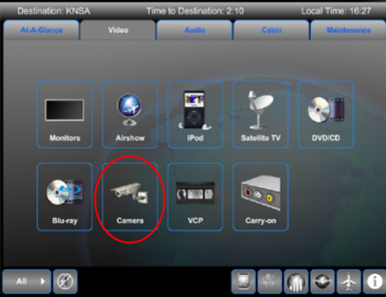
The CES provides control and display functions for the camera system. The CES provides an RS-485 bus to the Video Control Unit (VCU). The VCU provides individual control of each camera through this RS-485 interface. The CES provides MPEG encoding for each of the seven optional cameras. The camera video is distributed throughout the cabin digitally and available for viewing on any TSE or bulkhead monitor in the same way that entertainment video is available (multicast streaming). The cameras can be controlled by the following units:
- Galley TSE
- Cockpit Touch Screen
- MSL PCU Video Selection
- TSE Video Selection

External Camera System
The 'Securaplane' camera system for passenger entertainment comprises:
- One quad camera
- One belly camera
- One fin camera

Quad Camera
The quad camera is a four-in-one camera. It is installed on the fuselage belly providing quad view functionality with 360 degrees of viewing.


Belly Camera
The belly camera is installed flush into the lower fuselage, and provides the view directly below the aircraft. This camera offers up to 72X zoom (18X optical and 4X digital) with low light operation capability.

Fin Camera
The fin camera is a single high-resolution color unit mounted on the vertical fin. This camera offers an 88-degree field of view.

Eyeball Camera
Some aircraft have an eyeball camera installed in the overhead panel of the flight compartment providing a view aft at the cockpit door and cabin displayed on FMS CDU 3. The camera can be interfaced with the security system to record intrusions into the flight compartment for later playback.

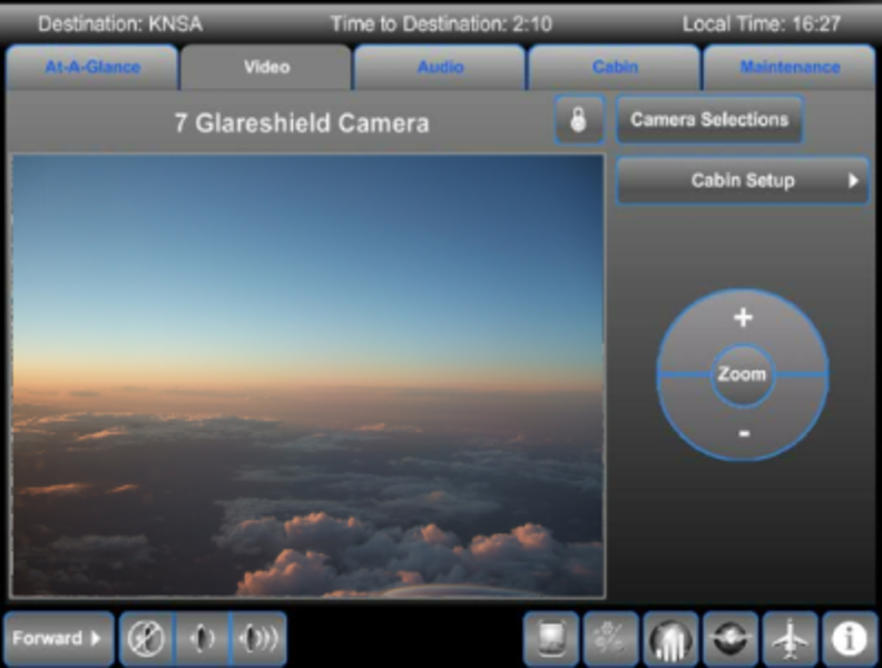
Glareshield Camera
The glareshield camera is capable of 40X zoom.


Camera Views
Camera views are available for viewing on all of the bulkhead monitors, the EFBs, and TSEs.
Carry-On Games
Each audio zone (forward and aft) in the cabin has a optional dedicated port available for connection of carry-on game devices. This port allows direct connection of the game device to the DTE for the bulkhead monitor in that zone. Direct connection of the game device is necessary to avoid the inherent latencies that would be introduced by digital encoding and decoding. The direct connection provided requires an NTSC signal source. A NTSC device could be connected to this port, not just games. Switching between a direct analog source and a network source is done within the DTE automatically and by way of network commands. The DTE provides the NTSC, VGA, and Ethernet inputs and provides an NTSC or VGA output. Portable game device audio is treated in a similar manner. Through the remote analog connections, the audio lines are connected directly to the DTE. The DTE encodes the analog audio as a PCM stream, which is then routed to the cabin speaker system or the passenger headset.

Satellite TV (Optional)
The CES has the optional the Airshow Tailwind 500 Satellite TV system (TW-5XX). The TW-5XX provides either two-channels or four-channels of TV. The TV system is a stand-alone system with respect to aircraft installation.
A subscription service is required for this option (www.myairshow.net).
A dedicated VEE is required to accommodate the TW-5XX. The VEE provides real-time encoding and subsequent multicasting of the TV channels. The TV channels are available for viewing in an identical manner as any other piece of source equipment. The only difference being is that instead of transport controls, the only controls associated with the TV system will be channel selection. The TW-5XX is a multi-region system with demonstrated performance in US, Europe, and the Middle East. Additional regions (e.g., Canada, Asia, South America) are expected to be available in the future. The TV receivers are controlled by way of an RS-485 bus provided by the VEE.
Tail-Mounted Unit (TMU) and Gimbal Electronic Module (GEM)
The TMU is an antenna located under the tail radome. The TMU receives RF signals from the satellite and transfers them to the GEM.
The GEM controls the TMU's azimuth and elevation steering motors to keep the antenna aligned with the satellite. It down-converts and processes the RF broadband signals, and sends them to the system signal processor.
System Signal Processor (SSP) and Configuration Data Module (CDM)
The SSP receives aircraft heading, position, pitch and roll information from the IRS. The SSP transmits the aircraft and satellite data to the GEM for positioning of the antenna. The SSP also down-coverts the first-stage intermediate frequency (IF) signals from the GEM for delivery to the intermediate frequency multiplexer unit.
The CDM preserves a copy of the configuration data from the SSP in nonvolatile memory, and can transfer the data back to the SSP when required.
Intermediate Frequency Multiplexer Unit (IMU)
The IMU receives IF signals from the SSP, then distributes the signals to receiver/decoder units, each with two separate television outputs.
The IMU is capable of supporting up to 16 receiver/decoder units.
Receiver/Decoder Units (RDU)
Each RDU contains to integrated receiver decoders (IRD) that can be for the same region, or for two separate regions. Additional RDUs can be installed to provide greater coverage.
The passenger controls the IRD to select a program channel. The RDU then decodes the channel and converts the IF signal to an audio/video program.
From the RDU, the signal makes its way to the CES and is ready for cabin broadcast on bulkhead monitors or TSEs.


Selection of Satellite TV is from the Video Content category. The availability of 6 satellite TV receivers indicates that there are 3 RDUs, one each having access to 2 regions.
A lock symbol indicates that a user is locked onto a channel in that receiver. A lock can be unlocked by clicking on the lock icon and the selecting Unlock for the appropriate seat location.
The RDUs along with their cooling fans, the VEEs and the SSP, are powered by 28 VDC from the DC PDEs. The remaining units receive electrical power from the units powered by the PDEs.
RF signals are received from the satellite by the tail-mounted unit and passed through the Gimbal Electronic Unit (GEM) to the SSP. The SSP routes the signal to the IF Multiplexer Unit (IMU) which makes the signal available to all RDUs. The VEE digitizes the SAT TV signals and sends these to the CES for distribution of the audio and video signals.
The control and selection of the satellite TV system is made from TSEs. The TSE sends tunneled commands over the ethernet which are converted to RS-485 in the VEE. The VEE sends commands over the primary RS-485 bus to RDU 1. A secondary RS-485 bus extends the primary RS-485 bus signals to the other RDUs and the SSP.

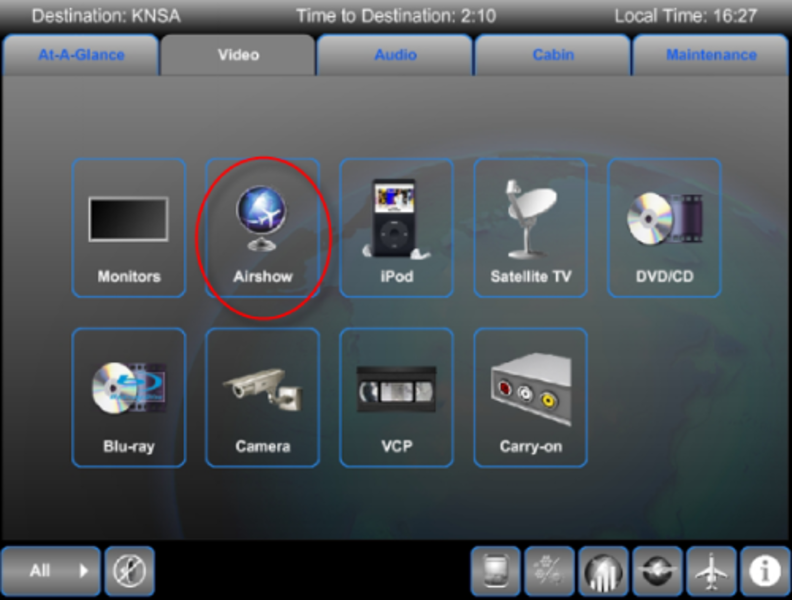
Airshow System
The airshow interactive (ASXi) moving map display and flight information system includes:
- Moving map
- Flight information
- World explorer maps
- Standard audio briefings
Airshow Global optional features include:
- Various map options such as Day-Night map with time zones
- Relative location indicator
- World explorer guide
- Static logo
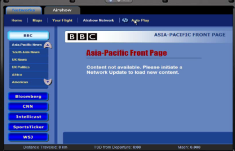
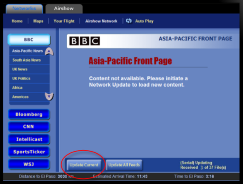
- Airshow network access to CNN, BBC, etc.
- Custom software
- Additional audio briefings
Some airshow options are configurable for color, language, map regions, display type, etc. Each aircraft ids different depending on the options selected. An annual subscription service is required. (www.myairshow.net).

The ASXi software resides in the moving map equipment (MME) in MCE 1. The MME provides a processor that is independent from the basic cabinet processor. The MME processor and hard disk host the software applications such as the moving map, audio on demand server, and video on demand server. To support airshow, the MME is continuously supplied with flight environment data from the FMS via ARINC 429 received by the PME through Ethernet. Airshow can only display flight-specific views if a flight plan has been programmed into the FMS.
Airshow network updates are transmitted from the airshow communication center ground station via the Iridium communication system (ICS) using an RS232 serial data link. Airshow network updates must be manually initiated by selection of a button on the Airshow Network page.
MME software uploads are performed using the maintenance laptop via an FTP session rather than the Collins CPAS 3000 software.

XM Satellite Radio System (Optional)
The XM satellite radio system provides satellite-based radio coverage for the North American continent.
One or two, four-channel receivers provide 4 or 8 independent channels of audio sources for the cabin. XM radio currently offers 68 commercial-free music channels, 33 channels of news, sports, talk and entertainment, and 16 dedicated channels of XM instant traffic and weather.
An antenna mounted on top of the fuselage provides communication with geostationary satellites.
XM satellite radio requires the user to subscribe to a service.
Analog XM radio signals are received from the satellites by the antenna.
The analog radio signals are processed by the receiver and then forwarded to the VEE. The VEEs digitize (encode into pulse code modulation PCM) the audio signals and place them on the ethernet.
Once on ethernet, the audio signals can be played over any headphone and over the cabin audio system.
Selection of XM Radio can be made at all TSEs. Control of the XM receivers is via RS-232 link from the VEE. Selections made at the TSEs are packetized and tunnelled to the VEE which de-encapsulates the signal to provide an RS-232 signal to the receivers.
A single antenna provides the XM satellite signal to one or both receivers.


iPod/iPhone Carry-On Connection
Apple iPods and iPhones can be connected to the CES. One or two charging cradles are provided close to other IFE equipment locations. Selection made on the iPod itself or at any TSE selects the output from the iPod. Audio only or audio/video signals are encoded by the VEE which digitizes the signals and places them on the ethernet.
Depending on selections made, audio signals can be heard over headphones and the audio distribution system. Video can be played on any TSE or bulkhead monitor.
When installed in its cradle, the iPod is controlled by the electronic control module (ECM). The ECM provides the interface between the iPods and the CES. Each ECM supports up to two iPods and provides:
- iPod authentication
- iPod control via RS-232 serial bus
- iPod charging via a USB
The ECM is provided 28 VDC from a DC PDE which also supplies the IFE fan. The ECM conditions and amplifies the audio/video signals to the CES. It also converts the 28 VDC input to 5 VDC for internal use and iPod recharging.
Control signals to change iPod settings are provided over ethernet from a TSE then converted to RS-232.
Audio signals are treated differently from audio/video signals. Audio signals are routed from the iPod, conditioned and amplified in the ECM, then sent to the VEE for encoding into PCM format. At the ZDE, the audio is decoded into analog for cabin speakers or headphones.
Audio/video signals are routed from the iPod to the ECM, then forwarded to the VEE for encoding into an MPEG 2 multimedia stream. The encoded stream is sent to a touch screen, or monitor, where the video is decoded and played. The audio stream is decoded in the TSE, then re-encoded and sent back to the ZDE. The ZDE decodes the audio back into analog to be heard over the headphones or cabin speakers.


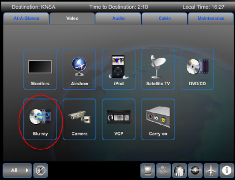
Blu-Ray Player (Optional)
This option installs Blu-Ray player(s) in the aircraft. HD quality videos can only be displayed on bulkhead monitors. The component video output (Pr/CR, Y, Pb/CB) of the Blu-Ray player is divided by video splitters to supply a number of monitors simultaneously.
The ethernet bandwidth limitation of 100 Mb/s prevents HD quality videos to be displayed on the standard TSEs via the CES.
Composite video output from the Blu-ray player is sent to the VEE for encoding into digital format.
The audio from the player is conditioned and amplified by an audio splitter. The audio signals are sent to a VEE.
At the VEE, the audio and video are combined and encoded into an MPEG-2 multimedia stream. The MPEG stream can then be viewed over ethernet on any touch screen.
Selections for viewing Blu-ray player video is made from the Video content category of the TSE.


05/20/16
Distribution
All the audio and video content in the cabin is distributed digitally over the Ethernet LAN. The system uses a 1 GB Ethernet LAN as the backbone for system communications including audio/video distribution. The audio and/or video encoders transform most, if not all, of the analog source content into streams of digital data. Decoders transform the digital data back into appropriate formats to drive the displays and headphones. In order to eliminate the audio/video timing/synchronization problems (lip sync) of video source content distributed to different destinations, for example bulkhead displays and passenger seat headphones, all video streams (MPEG encoded) are decoded at the display boxes (TSEs and/or DTEs). The display boxes concurrently re-encode the audio content into PCM stream and re-transmit the stream back onto the LAN. The PCM stream is routed to the appropriate ZDEs. All the audio streams are decoded at the ZDE. The ZDE generates an analog stereo output to drive the seat headphones and/or cabin/PA speaker amplifier(s).