


05/30/16
Overview
The electrical control of the APU consists of Starting and Ignition Systems, Electrical Sensors and Engine Electronic Control. It controls the operation of some components in related systems. The engine-controls system gets signals from and sends signals to many aircraft systems (directly and through ARINC).
The APU uses a computer-based electronic control system designed to:
- Maintain precise control of the APU under all conditions
- Enable an interface with all the APU subsystems
- Provide relevant displays in the cockpit

02/03/20
Automatic Control System
The automatic control system has a control unit and sensors. The control unit operates with 28 VDC from the aircraft battery buses. The sensors measure:
- The ambient conditions (an example is the air pressure)
- The properties of operation of the APU engine (an example is the engine speed)
The control unit uses the inputs from the sensors and inputs from other aircraft sources to calculate its control decisions. It uses these decisions to operate actuators in the airborne auxiliary power system and in other related aircraft systems (an example is the fuel system). These actuators control the supply of power, signals, and consumable materials to or from the APU. This lets the automatic control system do these primary functions:
- Cause the APU to start and its speed to increase to 100% in a specified time
- Cause the APU to supply a shaft (APU generator) or bleed-air load
- Control the fuel control unit to keep the APU at 100% speed for all load conditions
- Continuously monitor the operation of the APU to make sure it operates in specified limits
- Cause a usual or a protective shutdown of the APU
This system automatically causes a protective shutdown if the APU operation is unsatisfactory. It also causes a protective shutdown if there is an applicable built-in test (BIT) error or failure. Some of the conditions which cause a protective shutdown on the ground will not cause a protective shutdown in flight.
APU Control Panel
The only APU control provided for the operator in the cockpit is a rotary switch on the APU panel overhead, with three positions marked OFF, RUN and START. The switch may be left in either the OFF or RUN positions, but is spring-loaded from the START to the RUN position. All outputs from the switch are routed for appropriate action to the FADEC.

Full Authority Digital Engine Controller (FADEC)
The main component of the APU engine electronic control system is the single channel FADEC, also referred to as the Electronic Control Unit (ECU). The FADEC is packaged in a compact enclosure and mounted remotely from the APU, in aft equipment bay on the left side in an environment compatible with such electronic equipment.
Caution:
It is necessary to use electrostatic protection when you remove or install the FADEC.
The FADEC provides:
- Certification to Extended Range Twin Engine Operations (ETOPS) standards
- Achievement of in-flight start reliability of 100% by at least the second attempt
- In-flight shutdown rate of less than or equal to 0.20 event per 1000 APU flight operating hours
- Effective, maintenance-oriented built-in-test functions and displays, with all failure data being transmitted to the Centralized Aircraft Information Maintenance System (CAIMS) by the "ARINC 429" digital data bus, when queried by maintenance crew
While many of these features depend on the performance of the APU and accessories as well, the FADEC by itself ensures a superior level of reliability and functionality which assists in meeting or surpassing overall system requirements.
The FADEC is an electronic unit that receives electrical signals from the overhead control panel and the APU along with inputs and demands initiated by the applicable airplane systems. The FADEC uses these inputs to compute electrical/electronic output signals to control the operation of the APU engine.
The inputs to the FADEC include:
- Analog signals from the components in the airborne auxiliary-power system (an example is the inlet-door position signal from the inlet-door rotary transducer)
- Discrete signals from the components in the airborne auxiliary-power system (an example is the signal from the low oil-pressure switch)
- Analog signals from other aircraft systems (an example is the current-output signal from the APU-generator control unit)
- Discrete signals from other aircraft systems (an example is the APU run/off signal from the "APU" control panel)
- Digital data from the ARINC 429 data bus (an example is signals from the bleed management controller)
The FADEC´s control outputs to the APU include:
- Fuel metering
- Arming and regulation of the load control valve (LCV) and the surge control valve (SCV)
- Control of the loading/off-loading of the APU generator, and
- Control of APU's rpm and EGT
The FADEC also performs protective shutdowns of the APU engine, when allowable operating limits are exceeded. In addition, as part of its functions, the FADEC sends a variety of outputs to all applicable aircraft systems, which interface with the APU.
The components in the airborne auxiliary-power system are not the only ones to which the FADEC is directly connected. It also has interfaces directly with other systems and components, which include:
- The aircraft battery bus (the primary source of power for the FADEC)
- The avionics battery direct bus (the secondary source of power for the FADEC)
- The APU battery direct bus
- The "APU" control panel in the flight compartment
- The bleed-air control panel in the flight compartment
- The fuel distribution control panel
- The APU-feed shutoff-valve relay
- The APU starter-contactor unit
- The APU-generator control unit
To provide cockpit display, and for transmitting data queried by the CAIMS, the FADEC generates an ARINC 429 serial data bus signal, which serves as the medium for transmission and feedback of all such information. In addition, a Built-In-Test Evaluation (BITE) capability of the FADEC enables fault isolation to the LRU level.
FADEC Interfaces
The primary source of FADEC power is the 28 VDC Aircraft Battery Bus, while the Avionics Battery Direct Bus is the non-interruptible second source. This arrangement assures redundancy of power sources and enhances operational reliability of the APU. The FADEC automatically selects the Battery Bus as the power source if voltage of the bus stays at or above 22 VDC at FADEC power up plus 1 second, and continues to stay at or above 18 VDC (± 2 VDC) thereafter.
If either of the above two conditions is not valid, the FADEC selects the Avionics Battery Direct Bus automatically as the power source, provided the voltage is within the limits stated above.
Note:
When the primary aircraft battery bus drops below 10 VDC for more than 200 ms, the FADEC interprets this as a command to shutdown. The Avionics Battery Direct bus is then used to power the FADEC so it can perform a controlled shutdown (if the APU is operating), command the APU door closed, update the non-volatile memory (NVM), and deactivate ARINC communication.
During starts, the FADEC will automatically latch 28 VDC power after receiving the signal to "Run". During all operator-initiated shutdowns, FADEC power will remain latched until 5 minutes after the engine slows down to below 5% speed. This allows the rpm and EGT to be observed if necessary during APU shutdowns, in spite of their very slow decay.
FADEC sends commands to the door actuator to position the air inlet door. An RVDT on the actuator transmits the door actuator position to the FADEC. Positions of the door are not normally displayed in the cockpit. However, if the door position is not in agreement with the FADEC's command, then the actual position is annunciated in amber digits below the L and R Engine and APU Oil Quantity indications on the EICAS status page.
The FADEC transmits data of APU status and related parameters, as well as maintenance information in accordance with ARINC standards. All of the usual interfaces for the FADEC, by ARINC 429 data bus or directly connected, are through its ARINC 600 electrical connector. Data on parameters such as rpm, EGT, oil tank quantity and inlet door position (where applicable), are displayed on the EICAS Status Page, while crew alert messages are displayed on the CAS window of the primary page.
Maintenance related data are stored in FADEC's Non-Volatile Memory (NVM) for retrieval via queries through the CAIMS. More details on the NVM are discussed later under the sub-title "Recording and Storage Priorities".
The FADEC reads all applicable aircraft data continuously (every 200 milliseconds) from power-up initialization until power-down. This data is used for control of start and run cycles and for control of APU loading. The data may originate from the Engine Electronic Controller (EEC), the Bleed Management Computer (BMC), and/or the Electrical Management System (EMS), and it passes through DAU No. 3 to the FADEC.
The FADEC receives data of applicable airframe systems from the two independent channels of DAU 3. Primary source for data inputs is Channel A of DAU 3. If this channel (or data received from it), is determined by the FADEC to be invalid, it will automatically select Channel B for data reception. Data received on each channel is redundant. Therefore, dispatch of the aircraft with a failed DAU channel is permitted. Transmission of data between the DAU and the FADEC is on the ARINC 429 data bus.
In the event of failure of ARINC data communication the APU can still be started and utilized for electrical and pneumatic loads as follows:
- The Load Control Valve (LCV) will not respond to the AUTO position of the APU BLEED switch and will have to be opened and closed respectively via the manual ON and OFF positions of the switch
- The EGT and rpm indications will change to dashes
- Any faults that appear at the APU will not be reported


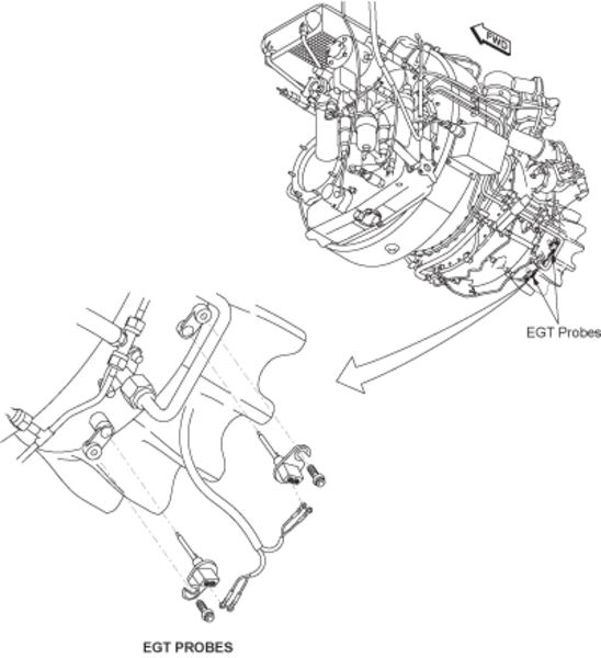
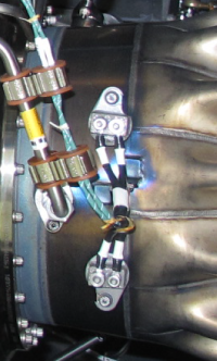
Exhaust Gas Temperature (EGT) Sensor
The EGT sensor measures the temperature directly from the APU exhaust gases. It installs on and into the turbine bearing support (the APU "tailpipe") and has flanges with slots to make removal and installation faster. The EGT sensor has two circuits which operate independently. The FADEC will continue to operate the APU if only one of these circuits operates. Each circuit has two thermocouples, and each thermocouple has a long probe and a short probe. These different probe lengths let the EGT sensor measure the exhaust gas temperatures more accurately. The EGT sensor measures continuous temperatures from 400 to 1300 °F (204 to 704 °C) and sudden temperatures as high as 1900 °F (1038 °C).
The EGT measuring system consists of two dual chromel-alumel closed bead thermocouple probes. The separate dual EGT probes are connected to the wiring harness by terminal lugs. Each EGT sensor is mounted in the eductor pipe and protrudes into the exhaust gas stream.
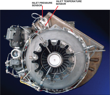
Inlet Temperature Sensor (T2)
The T2 sensor is mounted on the left aft side of the compressor air inlet duct, and senses the temperature of the air entering the inlet duct. The sensor is an electrical resistance temperature device that uses a nickel wire resistance element with an electrical resistance proportional to temperature. This signal is continuous, thus allowing actual temperatures to be monitored during APU operation.
The FADEC uses T2 sensor information in conjunction with the P2 sensor input to determine proper fuel schedule. Also, a T2 temperature which is too high indicates that the APU has an airflow in the opposite direction. If this occurs when the aircraft is on the ground, the FADEC will cause a protective shutdown of the APU. If this occurs in flight, the FADEC will send an advisory indication to the EICAS display.
During operation, the FADEC monitors the input of the sensors for an open or a shorted circuit. The FADEC will not cause an APU protective shutdown in case of a failure of either sensor. Instead, the FADEC will receive P2 and T2 inputs from the applicable Data Acquisition Unit (DAU), via the ARINC 429 No. 2 interface. If there are no inputs available from the ARINC interface, then the FADEC will default to a preset pressure and/or temperature and the APU will continue to run.
Note:
With either sensor failed, operation of the APU will not be normal. For troubleshooting, the FADEC may be queried via CAIMS.
Inlet Pressure Sensor (P2)
The P2 sensor is mounted on the upper left hand corner of the compressor air inlet duct, as viewed from the rear. It senses the air pressure in the APU air inlet duct and changes this pressure to an electrical signal for use within the FADEC.
The P2 sensor is a 0 to 15 psia (0-103 kPa) pressure transducer. It has strain-gage elements which are connected to make a Wheatstone bridge. It acts as a variable resistor when pressure is applied to the diaphragm within, and provides a variable output voltage to the FADEC. It receives a regulated 10 VDC power supply input from the FADEC and generates an output signal of up to 100 millivolts. The FADEC uses this output for control of circuits that are altitude sensitive. These circuits are:
- Fuel scheduling for ample surge margin of the compressor
- Starter cut-out schedule
- Surge Control Valve (SCV) Operation
Speed Sensor (Monopole)
The speed sensor/monopole provides RPM indications for "on-speed" control and for overspeed protection during APU operation. It has a permanent magnetic core, and it also has two coils which operate independently. The FADEC will continue to operate the APU if only one of those coils operates. But the FADEC must have continuous input from not less than one coil. If it does not, it will stop or prevent the operation of the APU. It is not possible to adjust the speed sensor, and calibration is not necessary. The speed sensor installs into the gearbox, and its flange has a slot to make removal and installation faster.
The speed sensor operates from the rotational movement of the four teeth on the compressor bearing nut (a part of the rotary group in the APU power section). It does not touch the compressor bearing nut, but uses magnetic reluctance to cause an ac output-voltage signal. This ac output-voltage signal changes as the teeth move through the magnetic field of the speed sensor. The ac output-voltage signal is in proportion to the RPM of the compressor bearing nut, which is installed on the turbine-rotor tie-rod. The FADEC reads the frequency of the changes in the ac output-voltage signal. It uses this data to monitor and control the APU speed during the ignition/start sequence and in all modes of APU operation.


05/30/16
Emergency Shutdown
The function of the emergency shutdown system is to cause a shutdown of the APU during an emergency condition.
The emergency shutdown system uses the APU-compartment emergency-stop switch and components from other systems to cause its operation.

The system operates when an emergency shutdown signal goes to the full authority digital engine controller (FADEC). The FADEC then immediately causes a shutdown of the APU. The three components from other systems which can send an emergency shutdown signal to the FADEC are:
- The APU fire handle
- The ELECTRICAL control panel (the BATT MASTER switch)
- The aft service control panel


05/30/16
System Operation
A start of the APU is initiated when the selector switch on the APU control panel in the cockpit is selected to the RUN position. Upon a RUN selection, a pre-start BITE feature is automatically initiated by the FADEC. This test is performed to verify the integrity of all the APU and FADEC-related electrical and electronic circuits, including internal APU and FADEC components.
When the BITE check is complete, the control switch is rotated and held in the START position for 2 seconds. APU rpm should increase to indicate that the starter has engaged.
Next, the switch is released and springs back to the RUN position. The APU then accelerates under automatic control of the FADEC.
If a failure is detected that would critically affect mission success, the FADEC inhibits starting of the APU until the failure is resolved. A CAS cyan APU SHUTDOWN message is displayed on the EICAS primary page to advise the crew of the existence of a critical fault at the time of the start attempt.
In addition, the failure is recorded in FADEC Non-Volatile Memory (NVM) for retrieval through queries to the Central Aircraft Information Maintenance System (CAIMS).
However, in the case of certain APU fault conditions, and if the aircraft is in flight, the FADEC reverts to an "essential mode" condition for APU operation. The FADEC sends an "APU protective bypass signal" to the ARINC 429 data buses. These faults generate a cyan APU FAULT (advisory) message that is displayed on the EICAS primary page. The crew then has two options in this case: continued APU operation, or APU shutdown.
Continuous speed signals are generated by (and within) the FADEC from rpm sensor inputs. These speed signals are used to automatically control a series of events at certain pre-scheduled rpm speeds.
Examples of these are: Initiation of fuel metering, ignition onset, starter relay drop-out, ignition termination and LCV RTL signal (to be discussed later).
During normal starts and operation, the FADEC will control ignition and regulate fuel automatically as required for ambient conditions. When the APU is running at 100%, the FADEC will maintain that speed within ± 1.0%.
Bleed air extraction will be adjusted automatically by the FADEC via the LCV to maintain EGT below a predetermined level.
Exhaust gas temperature and engine speed is continuously monitored by the FADEC. The FADEC will shut down the APU if engine speed exceeds 106% or if EGT exceeds the scheduled limits, which are biased by ambient conditions (P2 + T2).
Start Cycle and Power Management
The FADEC provides automatic management of bleed air and electrical power during Main Engine Starts (MES), usage of bleed air by air conditioning packs (i.e. by the ECS) and AC power supply to the aircraft electrical power system.
- At 5% APU speed, the FADEC powers the ignition unit, fuel torque motor, fuel shutoff solenoid valve, and fuel flow solenoid, allowing fuel flow to the primary fuel nozzles
- Above 35% engine speed, the fuel flow solenoid is de-energized open to allow a flow path to the secondary manifolds during acceleration and on speed operation. During low fuel flow requirements above 35,000 feet, the fuel flow divider is energized closed as determined by the FADEC
- Between 45 and 60% APU speed, depending on ground or in-flight start status, the FADEC removes power from the start relay, de-energizing the APU starter
As the engine accelerates, it is stabilized at 100% rpm, known as the steady state running condition of the APU.
- At 100%, a closed-loop speed feedback circuit in the FADEC assumes control and maintains the APU rpm constant (within ± 1. 0 percent)
- For loading the APU electrically/pneumatically, a separate Ready-to-Load (RTL) signal is sent to the applicable airframe system from the FADEC
- The RTL signal for electrical loading is made available by the FADEC as soon as the APU is operating at 99% for at least 2 seconds
- The RTL signal for pneumatic loading is not available until the APU has warmed-up for 60 seconds. When in the essential (fight) mode, or if the EGT at the time of APU start was above 149 °C, the FADEC waits for 2 seconds after 99% rpm, before sending out a pneumatic RTL signal

EGT System
When powered, the FADEC continuously monitors the thermocouple circuit. The two thermocouple probes provide redundant signals to the FADEC for fuel schedule trim, turbine temperature monitoring,and load control valve modulation. Loss of one probe will not affect APU operation. However, an advisory (cyan) message of APU FAULT will be displayed on the EICAS primary page to notify the crew of a potential problem.
In the nonessential (ground) mode, failure of both probes causes the FADEC to shut down the APU and inhibit starting. In addition, it also triggers a similar advisory message of APU SHUTDOWN to be displayed on the EICAS primary page.
In the essential (air) mode, failure of both probes does not cause a shutdown. Instead, the FADEC programs a 260 °C (500 °F) signal to allow pneumatic loading, and turns on the EICAS advisory message reading APU FAULT on the primary page.
The EGT sensor can be replaced separately and does not require any adjustments or calibration. Itis an "on condition" component requiring no service.
APU EGT Red Limit Schedule
The FADEC uses two different exhaust gas temperature (EGT) schedules to shut down the APU if an EGT exceedance has occurred. One schedule is specifically used for the acceleration of the APU until 95% speed is reached.The second schedule is used when the APU isoperating above 95% speed. In either case, the FADEC automatically shuts down the APU when an EGT exceedance occurs.
The following figure shows typical "red" limits for the EGT at several T2 temperatures and APU rpm. Changes to the prevailing altitude and air density at all times (and airplane Mach no. in flight) affect these EGT limits. This makes it impossible to provide operating crews specific maximum EGTs to monitor during starts and/or steady state (on speed) conditions.

EGT Trim Schedules
The FADEC of the APU utilizes three software trim schedules to prevent the APU from reaching an over temperature condition. These schedules are:
Acceleration Trim Schedule
During the APU start cycle, the FADEC looks at EGT No. 1, EGT No. 2, and inlet temperature (T2) to adjust the maximum fuel schedule.
If the EGT should reach the maximum prescribed limit, the FADEC will automatically cut back the fuel supply to prevent the EGT from exceeding the maximum limit.
(Main Engine Start) MES and ECS Trim Schedule
All APU pneumatic supply is extracted from the engine Pressure Compressor Discharge (PCD) via the LCV. When APU air is routed to the aircraft, the EGT increases proportionally to continue operation. Increased APU air demands will result in higher EGTs.
To prevent an APU over temperature condition, the FADEC uses EGT No. 1 and EGT No. 2 temperatures to control LCV position. The FADEC always uses the higher EGT reading as reference for trim functions.
Should the APU's EGT reach the maximum temperature limit of the trim schedule during MES or ECS operation, the FADEC will automatically start closing the load control valve to prevent the maximum trim limits from being exceeded.
Note:
All three of the EGT trim schedules will change with ambient pressure and inlet temperature. Higher inlet temperatures or higher altitudes will cause higher EGTs.
Note:
Conditions where the APU could "ride" (or stay at) the maximum MES, ECS or Acceleration Trim Schedule are:
- A degraded APU power section
- A hot day condition
- Higher altitudes, or
- A leak in the APU bleed air or where applicable, in the aircraft ducting
EGT Shutdown Schedules
The ECU utilizes two different exhaust gas temperature (EGT) schedules to shut down the APU if an EGT exceedance has occurred. One schedule is specifically used for the acceleration of the APU until 95% speed is reached.
The second schedule is used when the APU is operating above 95% speed. The FADEC will automatically shut down the APU when an EGT exceedance occurs.
The APU ECU receives information from the APU EGT thermocouple rakes No. 1 and No. 2. The ECU will always use the signal of the higher reading EGT rake for its shutdown schedules.
The FADEC contains two defined shutdown schedules within its internal circuitry: Acceleration and On-Speed. The schedules are permanently programmed and cannot be altered by the operator.
The Acceleration Shutdown Schedule utilizes the APU speed (%) to determine the exact EGT exceedance limit, whereas the On-Speed Shutdown Schedule utilizes APU inlet temperature (T2), and pressure (P2) to determine the exact EGT exceedance limit.
Temperature Indication
The EGT system consists of a single temperature sensing unit with two probes. The probes provide redundant signals to the FADEC for fuel schedule trim, turbine temperature monitoring, and load control valve modulation. The APU is protected from over temperature during acceleration by protective features incorporated in the FADEC. Loss of one probe will not affect APU operation. An APU FAULT advisory message will be posted if one probe fails.
In the non-essential (ground) mode, failure of both probes will cause the FADEC to shut down the APU and inhibit the next start attempt. In the essential (flight) mode, failure of both probes will not cause a shutdown. An EICAS caution message APU EGT SENSORS is posted, and the FADEC reverts to a preset temperature signal (260°C) to allow pneumatic loading and normal operation of electrical power. Because of the loss of EGT control, the APU should be shut down unless required for another contingency.
P2 and T2 Sensor Operation
During operation, the FADEC monitors the input of the sensors for an open or a shorted circuit. The FADEC does not cause an APU protective shutdown in case of a failure of either sensor. Instead, the FADEC receives P2 and T2 inputs from the applicable data acquisition unit (DAU), via the ARINC 429 no. 2 interface. If there are no inputs available from the ARINC interface, then the FADEC defaults to a preset pressure and/or temperature and the APU continues to run.
Note:
With either sensor failed, operation of the APU may not be normal. For troubleshooting, the FADEC may be queried via the CAIMS system, and the applicable component replaced.
Monopole Operation
Two speed sensors (Monopole) provide indicated speed for sequencing of events during a start, on-speed control and overspeed protection. During operation, the FADEC monitors the speed sensors and, should either sensor fail, an APU FAULT advisory message is displayed on EICAS. The FADEC monitors the monopole output to sequence pre scheduled events during APU operation and to prevent overspeed. The sequence of events is:
- Initiate fuel flow
- Ignition
- Starter cutout
- Acceleration fuel schedule
- Ignition termination
- Alternator load
- Trigger Ready To Load (RTL) signal (discussed in Section F)
A failure of either sensor will not cause an APU protective shutdown to occur. However, a failure of both sensors will cause an APU protective shutdown both on ground and in the air. The EICAS advisory message APU SHUTDOWN is posted with this fault.
APU Shutdowns
Normal
Selecting the APU control switch to OFF will send a signal to the FADEC, which deactivates the Ready-To-Load (RTL) signal and all applicable APU loads. The FADEC commands the engine to run down to 70% rpm at a rate of 0.5% per second for 60 seconds, if it is in flight at a pressure altitude of less than 20,000 feet or on the ground, before shutting it down. If the APU is at 20,000' or above, the FADEC will allow it to operate at 100% for 60 seconds before shutting it down. This is called the "cool-down", or, "decreased temperature" mode.
All shutdowns above are accomplished by a simulated 106% overspeed signal from the FADEC to test the overspeed circuitry.
During the cool-down period, if the control switch is moved back to RUN, the APU will reverse its trend, accelerate normally back to 100% rpm as per FADEC's schedule, and revert to normal operation.
When the speed drops below 25%, the FADEC commands the inlet door closed. The FADEC also downloads the duration of APU operation from the hour-meter, updates its own "hours-run" memory and de-activates the hour-meter below 95% rpm. APU-related cockpit indications and EICAS displays will be de-activated when the APU door is fully closed.
Emergency
The following are not to be used as normal shutdown procedures. However, in emergencies, any one of the four methods below will assure immediate shutdown of the APU, without the "cool-down" mode:
- The Battery Master Switch is turned OFF (no AC power ON), or
- The APU fire handle is pulled (whether APU is on fire or otherwise), or
- The APU STOP button on the External Services Panel located below the cargo door is pushed in momentarily and released, or
- The APU STOP button in the APU compartment is pushed in
All four are permitted when the aircraft is on the ground, but only one is applicable when you are in flight. All four procedures send an emergency shutdown signal to the automatic control system. The automatic control system then causes the flow of fuel to the APU to stop. This causes the APU engine to immediately start to decrease its speed, and to stop after a short time. After a signal for an emergency shutdown, the APU stops without its usual 60 seconds in the decreased-temperature mode.
In order to restart the APU, after an emergency shutdown, it is necessary to ensure that the Battery Master switch is ON, and the APU control switch is first moved to OFF, to reset the FADEC, before attempting an APU start.


08/08/17
System Monitoring
The built-in-test equipment of the FADEC includes the hardware and software that determine and communicate either an internal fault of the FADEC or an external fault of the APU control system. The FADEC hardware and software have built-in test (BIT) functions. The built-in test equipment (BITE) monitors the FADEC internal operation and the performance of the components which the FADEC controls. The BITE also transmits BIT error and failure data, which the FADEC uses to cause an applicable display on the EICAS status page. All BIT error and failure data is also transmitted to the CAIMS through the ARINC 429 data bus. If the BITE finds a dangerous condition, the FADEC will immediately cause an APU protective shutdown (without a decreased-temperature mode). The FADEC can cause a protective shutdown during the APU ignition/start sequence, or during APU operation (in all modes and loaded or not-loaded conditions). During flight, the FADEC logic lets the APU continue to operate with some conditions that will cause a protective shutdown when on the ground. For such flight conditions, the FADEC causes the applicable advisory, caution, or warning display on the EICAS status page. Failure detection consists of a prestart BITE and a continuous BITE.
Power-On Built-In Test
The FADEC enters a power-on self-test after receiving 28 VDC power (battery master switch ON). The FADEC circuitry is activated, initialized, and tested to verify that the FADEC is capable of controlling the APU. After initialization is complete, the FADEC activates ARINC communication and enters idle mode (awaiting RUN command).
Prestart BITE
The FADEC enters prestart BITE when the APU switch is selected to RUN. This tests the operational capability of the APU. The prestart BITE may also be activated in CAIMS.
During the prestart BITE, the FADEC checks the following items:
- Cockpit control and applicable valve/inlet door switches for position
- Solenoids and torque motors for opens, shorts,and over current condition
- Sensors (such as T2, P2, rpm and EGT) for their range of operation
Continuous Built-In Test
During continuous BITE, the FADEC continuously tests its internal components, such as memory, power supply, and processor operation. The continuous BITE also detects electrical failures of the sensors, driver circuits, and driver loads in addition to internal FADEC faults.
Protective Shutdowns
The FADEC has the authority to accomplish a protective shutdown of the APU when BITE indicates continued APU operation might cause damage.
When a protective shutdown has been initiated, the BITE feature is inhibited from triggering any more shutdown signals, or from detecting any other LRU faults during the APU roll down.
Though some protective shutdowns do not terminate APU operation in flight, the FADEC stores the failure and signals the CAS to display the appropriate message to the crew. If the flight crew turns the APU switch to OFF upon receiving this message, the FADEC shuts down the APU and bypasses the cool down cycle.
A variety of APU faults (including those in the following table of faults that can trigger protective shutdowns of the APU) can be stored in the nonvolatile memory (NVM) of the FADEC. The NVM is capable of storing 22 fault records in each of the 16 most recent flight legs.
| SHUTDOWN CONDITIONS | OPERATING MODE | CAS |
|---|---|---|
| FADEC Failure: Internal FADEC failure (i.e. CPU, watchdog timer, etc.) | Ground/Flight | APU SHUTDOWN |
| Inlet Door: Inlet door position sensor indicates that the door is closed Prior to starter engagement: 30 sec After starter engagement: 600 msec | Ground/Flight | APU SHUTDOWN |
| Fire/Emergency: Fire signal received by FADEC | Ground/Flight | APU SHUTDOWN |
| High Oil Temperature: Oil temperature greater than 300°F for 10 seconds while the APU is on speed |
Ground
Flight* |
APU SHUTDOWN
APU OIL HI TEMP |
| Overspeed: Speed greater than 106 percent (as detected by FADEC hardware or software) | Ground/Flight | APU SHUTDOWN |
| Loss of EGT Detection: Loss of both EGT rakes and/or FADEC signal conditioners |
Ground
Flight* |
APU SHUTDOWN
APU EGT SENSORS |
| Low Oil Pressure:Low oil pressure condition detected for 15 seconds with the APU on speed |
Ground
Flight* |
APU SHUTDOWN
APU OIL LO PRESS |
| No Crank: APU speed less than 5 percent X seconds after starter relay is enabled; X = 12 seconds for warm oil, X = 50 seconds for cold oil | Ground/Flight | APU SHUTDOWN |
| No Accel: Acceleration less than 0.05 percent/sec for 15 seconds | Ground/Flight | APU SHUTDOWN |
| LOP Switch Failed |
Ground Flight* |
APU SHUTDOWN APU FAULT |
| Slow Start: Start period timers expired | Ground | APU SHUTDOWN |
| No Flame: No light-off detected within 17 seconds after fuel solenoid is enabled or speed greater than 18 percent for 5 seconds | Ground | APU SHUTDOWN |
| Reverse Flow: T2 greater than 350F for 5 seconds |
Ground
Flight* |
APU SHUTDOWN
APU REVERSE FLOW |
| Loss of Speed: Loss of monopole signals | Ground/Flight | APU SHUTDOWN |
| Loss of DC Power: Loss of primary and secondary power for more than 200 msec | Ground/Flight | APU SHUTDOWN |
| Loss Overspeed Protection: Failure of either the fuel solenoid and/or FADEC overspeed circuit | Ground/Flight | APU SHUTDOWN |
| Underspeed: Speed has reached 100 percent, then drops below 80 percent for 5 seconds | Ground/Flight | APU SHUTDOWN |
| Overtemperature: EGT exceeds scheduled limit |
Ground
Flight* |
APU OVERTEMP |
| Fallback: Speed drops below 25 percent after starter cutout | Ground/Flight | APU SHUTDOWN |
| Failed to Relight Shutdown: Speed drops below 45 percent when APU fails to relight after a blowout. | Ground/Flight | APU SHUTDOWN |
| Generator Overtemp Shutdown: APU shuts down 5 seconds after receiving indication of generator overtemp via ARINC |
Ground
Flight* |
APU SHUTDOWN |
* The protective shutdown is inhibited when the aircraft is in-flight. |
||
System Test
There are two fixed leading edge wing leak detection loops, one in each fixed leading edge. Each loop is attached to the frame adjacent to its related wing supply duct assembly. At 460 °F (238 °C) and above, the loops sense a leak. When a leak is sensed, the EICAS primary page shows a WING A/I LEAK message.
Initiated Built-In Test – CAIMS
The CAIMS Portable Maintenance Access Terminal (PMAT) can be utilized on the ground to access specific tests and data monitoring of the APU Controller (FADEC) in the following areas:
- APU Controller (FADEC) Self-Test
- APU Door Rigging Routine
- APU Status, and
- APU Data Status
APU FADEC Self-Test Selection
The APU FADEC self-test checks the status of the APU electrical control system and stores the APU door position offset for use in "auto-zeroing" of the door position. This test can be initiated only when the APU is not operating and WOW is true for the aircraft.
Upon selecting the self-test routine, a precondition screen is displayed to provide an overview of the test and potential safety concerns.
Door Rigging Selection
An interactive door rigging feature is built into the logic of the APU FADEC. This door rigging feature can be used by maintenance personnel in conjunction with the maintenance manual, to facilitate proper rigging of the APU doors. The door rigging feature can be used only when the APU is not running and the aircraft is on the ground (WOW).
APU Status Page Selection
This selection on the PMAT provides Status Page displays of the APU operating modes as transmitted by the FADEC. The operating modes are designated as INACTIVE or ACTIVE.
Active modes are indicated by a "1" in the right hand, and inactive modes are indicated by a "0". When the Status Page selection is made, the following operating modes are displayed:
- Pre-Test Sequence
- FADEC Idle -Waiting Time for Start
- Fuel Request Signal
- Start Signal
- Inlet Door in Transit
- Start Sequence
- Generator RTL (Ready to Load) Signal
- Bleed Air RTL signal
- Operation in the Essential Mode
- Operation of the LCV in the Manual Mode
- Cool down Sequence
- Shutdown Sequence, and
- Maintenance Sequence
APU Data Status Page Selection
This selection on the PMAT displays APU parameters that are monitored by the FADEC. The parameters are displayed in two pages, with the speed and EGT values shown at the top of each page.
