


05/30/16
Overview
The engine fuel and control system supplies clean (filtered) fuel to the auxiliary power unit (APU) combustion chamber. The system supplies filtered fuel in the correct quantity and at the applicable pressure.
The full authority digital engine controller (FADEC) controls the operation of the engine fuel and control system. The FADEC energizes this system after it gets a signal of RUN from the APU control panel. The FADEC then sends a signal to the fuel distribution control panel, which tells the fuel system to supply fuel from the applicable aircraft tank. At the same time, the FADEC sends a 28 VDC signal to open the APU feed shutoff valve relay. This lets fuel go through the fuel inlet hose and into the fuel control unit (FCU). The FCU pressurizes the fuel.
The FADEC controls the quantity of fuel flow. At 5% APU speed, the FADEC sends a signal to open the fuel shutoff solenoid. Fuel then flows to and divides at the primary fuel manifold and the fuel solenoid valve. The primary fuel manifold sends the fuel to the fuel nozzle assembly, which causes a spray in the combustion chamber. When the fuel flow becomes approximately 80 lb/h (36 kg/h), the FADEC sends a signal to open the fuel solenoid valve.
Fuel then flows to the fuel flow divider valve, which opens in proportion to the fuel pressure. This lets fuel flow into the secondary fuel manifold and increases the quantity of fuel spray in the combustion chamber. At the same differential fuel pressure, the primary spray opening (in the fuel nozzle) flows only one half as much fuel as the secondary spray opening. The FADEC can increase, decrease, or stop the flow of the secondary fuel as applicable. To do this, it opens or closes the fuel solenoid valve or causes the FCU to adjust the fuel pressure.
The FADEC causes the fuel flow to stop when one of many sources sends a signal. For a usual shutdown, the FADEC lets the fuel continue to flow at an applicable level to cause a 60 second decreased temperature mode. After that time, the FADEC sends a signal to close the fuel shutoff solenoid to stop the supply of fuel. For an emergency shutdown, the FADEC will immediately cause the supply of fuel to stop, without the decreased temperature mode.
The maximum fuel consumption for the APU is 325 lb/h (147.41 kg/h), when the APU is loaded.
There are two tube assemblies which drain fuel from the APU. The fuel control drain tube connects to the FCU at the seal witness opening and drains fuel or oil leakage (if there is a defective FCU shaft seal, there will be leakage at the seal witness opening). The turbine case drain tube drains the fuel which does not burn from the APU. It connects to the orifice fitting assembly, which is installed in the turbine case.
The APU fuel system is controlled automatically by the FADEC and requires no other control or adjustments other than operator-initiated starts and stops. The system requires a stable supply of fuel at a pressure of 10 to 55 psig, and DC electric power input. On startup the system meters the correct amount of fuel, progressively increasing fuel supply to support combustion with smooth acceleration, until the rated steady state speed (i.e., 100% rpm) is reached.
The APU is protected from over temperature during acceleration by the FADEC. At 100% rpm, fuel flow is modulated as necessary to meet the demands of varying pneumatic and electrical loads while maintaining a constant engine speed.
The APU fuel system is fully automatic and requires no other operator control or field adjustments other than operator-initiated starts and stops.
Features of the APU fuel system:
- The system is controlled by the FADEC (also called the ECU)
- The system requires a stable supply of fuel at a pressure of 10 to 55 psig, and DC electric power at an input of 24 volts
- Upon a startup signal, the system continuously meters the correct amount of fuel, progressively increasing fuel supply to support combustion with smooth acceleration, until the rated steady state speed (i.e., 100% rpm) is reached. The APU is protected from over temperature during acceleration by the FADEC
- At 100% rpm, fuel flow is modulated as necessary to meet the demands of varying pneumatic and electrical loads while maintaining a constant engine speed


05/30/16
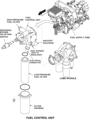
Fuel Control Unit (FCU)
The FCU is attached to the oil system lubrication module using a quick release V-band clamp. The FCU drive splines are lubricated by oil flow from the oil pressure pump. Oil is returned through an internal gallery within the drive spline.
The FCU pulls low pressure fuel from the aircraft through the sediment filter element (unless the impending bypass valve and switch is open). Because of the sediment filter element, the FCU will usually operate satisfactorily if the fuel has contamination. The high pressure pump pressurizes the fuel, which then divides and goes to:
- The high pressure relief valve (which controls the maximum output pressure from the high pressure pump if there is a blockage in the system)
- The fuel strainer element (which gives protection to the downstream components if a failure of the high pressure pump causes contamination)
- The differential pressure regulator (which also gets a pressure input from the low pressure fuel)
The high pressure fuel flows through the fuel strainer element and then to the torque motor metering valve. The torque motor metering valve has interfaces with the FADEC and the differential pressure regulator. The FADEC sends signals which put the torque motor metering valve in the applicable position and the differential pressure regulator adjusts the pressure across it.


The FADEC then causes the torque motor metering valve to adjust the fuel to an applicable pressure and flow rate. The output of the torque motor metering valve, which is the fuel pressure, flows to the pressurizing valve. The pressurizing valve helps to control the pressure of the fuel. The fuel shutoff solenoid, with input from the FADEC, controls the flow of the fuel.
The FCU provides metered fuel to ten fuel atomizers in direct proportion to signals received from the ECU. This is enabled by a positive displacement, gear type, high pressure pump within the FCU, which provides flow capability in excess of the demands of the APU engine.
The FCU has a single electrical connector. A witness drain port is located on the underside of the mounting flange and connects to the drain mast.
Sediment Filter Element
The input to the FCU is from aircraft pressurized APU fuel feed system, supplied via the APU firewall shutoff valve (APU SOV). When the APU switch on the overhead APU panel is set to RUN, the DAU 1 sends an APU START signal to the APU SOV, and the valve opens. The fuel entering the FCU is routed via a disposable 40-micron inlet filter to the high-pressure pump.

Impending Bypass Valve and Switch
The impending bypass valve-and-switch is in the housing of the FCU. It measures the differential pressure between the fuel input and the fuel output at the sediment filter element. When the sediment filter element starts to become clogged, this differential pressure increases. When it becomes 5 to 7 psid (35 to 48 kPa), the impending bypass valve-and-switch sends a signal to the FADEC. The FADEC then sends an indication to the EICAS display (APU FAULT) and causes a message to show in CAIMS. If the sediment filter element is not replaced, the differential pressure will continue to increase. When it becomes 7 to 9 psid (48 to 62 kPa), the impending bypass valve-and-switch opens. This lets dirty fuel bypass the sediment filter element and go into the engine fuel-and-control system.
Fuel Pump and High Pressure Filter/Screen
The shaft of the FCU drives the integral high pressure fuel pump internally. It consists of a positive displacement element, comprising a pair of mating gears, lubricated by the fuel itself. The fuel pump has an output capacity greater than engine requirements. The fuel pump output passes through a 70-micron wire-screen high-pressure filter. The filter can be removed without removing the FCU.
Torque Motor, Metering and ΔP Regulating Valve
The fuel metering system ensures that a constant differential pressure (50 psid) is maintained across the metering valve opening. Fuel flow across the valve will be proportional to the size of the opening.
A torque motor controls the metering valve opening that varies the amount of fuel to the atomizers. To more accurately control the volume of fuel delivered to the engine, a differential pressure (ΔP) regulating valve is placed in parallel with the metering valve. The ΔP regulating valve maintains a constant pressure drop across the metering valve at all times.
When the engine is running at a constant speed, the pump delivers a constant fuel flow. The ΔP regulating valve returns fuel in excess of that required by the atomizers to the pump inlet. In this way, the pump output is constant, but fuel flow to the engine could vary within limits according to engine demands (which may in turn, vary due to varying bleed air/electrical loads).
The FADEC commands the metering valve to increase or decrease fuel flow to the APU. The position of the ΔP regulating valve is automatically coordinated with the position of the metering valve. The design of the ΔP valve and its location in the system enable it to be operated by the changes to the differential pressure across it.
For example, when the engine requires more fuel, the metering valve is commanded to open further by the FADEC. At the same time, the ΔP regulating valve is moved further towards its closed position, due to the resulting change in ΔP it senses. This reduces the fuel bypass back to the pump inlet by a corresponding amount, and thereby compensates for the increase in fuel flow through the metering valve to the atomizers.
When the metering valve moves, the pressure drop across it changes. As this pressure change occurs, the ΔP regulating valve is repositioned, which maintains a constant pressure drop across the metering valve. This makes metered flow to the atomizers proportional to the size of the metering valve opening only, and not a function of pressure drop.
Likewise, when the engine requires less fuel for its operation, a similar series of events will take place in reverse, with the same results.
High Pressure/Ultimate Relief Valve
This valve protects internal components from overpressure damage during engine shutdowns when the FADEC commands the fuel shutoff solenoid valve closed. To prevent this, an Ultimate Relief Valve is installed in the FCU, parallel with the metering valve. The high pressure/ultimate relief valve begins to open at 900 psig, and bypasses fuel to the inlet side of the pump when open. The valve is most likely to open when the engine is shut down.
Fuel Shutoff Solenoid Valve
The fuel shutoff solenoid valve is located downstream of the metering valve. It is spring-loaded closed, and opens electrically upon an input from the FADEC. During the APU start sequence, this valve will receive a command signal from the FADEC to open at 5% speed.
On normal or fault shutdowns, the valve is de-energized closed by the FADEC. The fuel shutoff solenoid valve is mounted on the fuel pump assembly in the FCU, and is not an LRU.

Secondary Flow Divider Shutoff Valve (SOV) and Fuel Flow Divider Check Valve
The secondary flow divider SOV is located between the fuel shutoff solenoid valve and the fuel manifolds. Its purpose is to sequence and distribute fuel to the secondary fuel manifold for proper starting and operation on the ground and in flight.
The fuel flow divider consists of an in-line shutoff valve (SOV) and a check valve. The check valve is spring-loaded closed and will open when the fuel pressure in the flow divider input line is between 115 and 135 psig.
The secondary flow divider SOV is spring-loaded open. The solenoid is energized closed by commands from the FADEC. During APU ground starts, the valve is closed at 5% rpm. Under these conditions, only primary fuel is used for combustion.
The primary and secondary fuel manifolds connect to the flow divider and route fuel to the fuel injector nozzles (10 dual orifice nozzles).
When the FADEC fuel schedule requirement reaches 70 pph (approximately 35% rpm), it will de-energize the solenoid. Fuel is then directed to the normally closed fuel flow divider check valve. When fuel pressure reaches 115-135 psig, the fuel flow divider check valve will open and fuel is delivered to the secondary manifolds and nozzles, initially for acceleration later, for "on-speed" operation.
At altitudes above 35,000 feet, the secondary flow divider SOV will be closed by the FADEC due to low fuel flow demands. This ensures better control of the primary nozzle pressure and prevents fuel dribbling through the secondary orifices, which could cause burning of the combustion liner, or the creation of localized hot spots in the combustion chamber.
The solenoid of the secondary flow divider SOV is tested by the FADEC during ground starts to confirm serviceability of the solenoid valve.
To ensure an even distribution of fuel around the entire combustor, the nozzle flow rates are matched during initial assembly of the engine. Uneven fuel distribution in the annular combustor could produce uneven expansion, stress, cracking and warping of the combustion chamber liner.
The fuel flow divider valve is a differential pressure check valve that controls the volume of the secondary fuel flow. It connects between the fuel solenoid valve and the secondary fuel manifold. No fuel gets to it unless the fuel solenoid valve is open (not energized). The flow through the fuel flow divider valve is in proportion to the pressure differential between its upstream and downstream openings. It is set to open at 125 ±10 psid (863 ±69 kPa).


Pressurizing Valve
The pressurizing valve is located between the DPR/torque motor metering valves and the fuel solenoid valve. It prevents fuel from flowing to the fuel solenoid shutoff valve until proper operating pressure is attained at the differential pressure regulator and torque motor metering valves.
05/30/16
Fuel Solenoid Valve
The fuel solenoid valve is a secondary fuel flow divider solenoid valve that is usually open. It is operated electrically. It attaches to a bracket on the bottom of the APU and it connects to the fuel flow divider valve. It also connects to the flow divider supply tube. When the FADEC energizes it, the fuel solenoid valve closes to prevent the flow of the secondary fuel. The fuel solenoid valve is energized (closed) for these conditions:
- On the ground during the ignition/start sequence when the APU speed is from 7 to 55%
- At flight altitudes less than 38,000 ft (11,580 m) when the APU speed is from 7 to 75%
- At all APU speeds when the flight altitude is more than 38,000 ft (11,580 m)
Flow Divider Supply Tube
The flow divider supply tube is a rigid metal tube. It connects to the FCU output opening and to the fuel solenoid valve. It supplies fuel to the fuel solenoid valve and the primary fuel manifold.
Dual Orifice Atomizers
Ten dual orifice (duplex) type pressure atomizers are used in the fuel system. The dual orifice fuel injector (fuel atomizer) has a single tip with two discharge orifices and two fuel inlet fittings.
The primary function of the assembly is to atomize fuel into a fine spray in the APU combustion chamber. An air shroud, that directs compressor discharge air to the nozzle tip to mix with the fuel as it is sprayed into the combustion chamber assembly, surrounds the nozzle.
A positioning pin on the body acts as a guide, for positioning both the nozzle and the air shroud. When installing the nozzles into the turbine plenum, ensure that the air shroud and nozzle assemblies are properly aligned. This prevents damage to the positioning pins, which can cause APU starting and performance problems.
It should be noted that the nozzles are not field-cleanable.
Combustor Drain
A turbine plenum orifice drain fitting (0.060") drains fuel that may accumulate in the plenum following an unsuccessful start attempt. The drain is located at the lowest point in the plenum to ensure complete drainage. Draining the excess fuel prevents a possible hot or torching start. The orifice remains open at all times and, because it is large, it is unlikely to be blocked by ordinary plenum chamber debris.
The orifice fitting is connected to an overboard drain. If the drain is clear, during APU operation, a flow of air vents out the drain.

System Operation
The fuel system is a fully automatic electronic control system. The fuel control unit provides metered fuel to 10 fuel injection nozzles, regulated by signals received from the FADEC.
During start the fuel system provides the correct amount of fuel to support combustion and for smooth acceleration of the engine to full rated speed. Once on speed, fuel flow is modulated as necessary to meet the demands of varying pneumatic and electrical loads, while maintaining a constant 100 ± 1% speed.
When the rotary selector switch on the pilot's APU panel (overhead) is moved to the RUN position, an aircraft fuel pump pressurizes the fuel system. Low pressure fuel is now directed through the fuel filter to the inlet of the high pressure pump in the FCU.
Next, the rotary selector switch on the APU panel is moved momentarily to the START position. The APU FADEC will engage the APU starter, the APU engine and the high pressure pump will start turning. The high-pressure fuel pump produces more fuel flow than needed by the APU to support requirements under any load condition.
As the pump starts turning, the high pressure fuel output from the pump will enter the metering valve. Fuel flow metering is accomplished by the use of a "balanced clevis", which is moved across an elongated orifice in the metering valve. The torque motor controls the clevis.
Increasing the current to the torque motor moves the clevis to increase the orifice area, and decreasing the current decreases the orifice area. When zero current is applied, the clevis moves to its lowest stop and blocks fuel flow.
The relationship between torque motor current and fuel flow is:
- Max Flow - 325 lb/hr at 250 ma
- Min Flow - 7 to 13 lb/hr at 20 ma
- Start Flow - 25 to 30 lb/hr at 35 ma
Whenever a SHUTDOWN is initiated by a protection system of the APU, the current to the torque motor is automatically removed, causing the metering valve to fully close.
Next, metering valve output is routed to the fuel shutoff solenoid valve, which is spring loaded closed. It is opened when the associated solenoid is energized at 5% speed, and allows fuel to be directed to the secondary flow divider SOV, manifolds and nozzles. It closes to shut off fuel during all normal and automatic shutdowns.
The secondary flow divider SOV sequences and distributes metered fuel to the fuel manifolds and nozzles. It is energized closed at 5% to direct fuel to the primary manifolds alone for initial combustion.
At a FADEC schedule of 70 pph fuel flow (approximately 35%) engine speed, the secondary flow divider SOV is de-energized open to allow fuel flow to the secondary manifolds for acceleration and on-speed operation.
Ten dual orificed atomizers direct the primary and secondary spray patterns to support combustion, and prevent flame paths from coming into direct contact with the combustion chamber surfaces. Upon shutdown, excessive fuel will be drained from the orifice type plenum drain at the six o'clock position of the combustor case.

09/28/20