


Overview
The function of the engine system is to change heat energy from the combustion of a fuel-air mixture into shaft or pneumatic power. The engine can use its shaft power to turn the APU generator to make AC voltage. Its pneumatic power can supply the environmental control system or start the aircraft engines.
The functions of the engine are:
- To supply shaft power to operate the APU generator when necessary
- To be an alternative source of bleed air
The engine is a gas turbine engine, and it has a power section and a gearbox. The full-authority digital engine-controller (FADEC) controls the operation of the power section.
The RE220 Engine consists of the following major components:
- A single-stage Centrifugal Compressor
- A two-stage Axial Flow Turbine
- An Accessory Gearbox with an Integral Oil Reservoir
- A Common Shaft to connect the three components above
- An Annular Reverse Flow Combustor
- An Exhaust Duct and an Eductor
The main rotating group of the RE220 engine consists of a single-stage centrifugal flow compressor and a two-stage axial flow turbine on a common shaft which drives the accessory gearbox. The compressor is compact and equipped with a Load Control Valve (LCV) and a Surge Control Valve. The accessory gearbox drives an AC generator, to power the aircraft electrical buses.


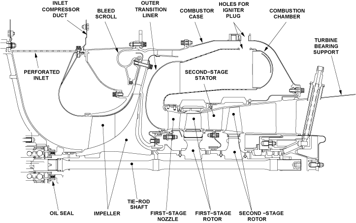
Power Section
The impeller pulls in ambient air, compresses it, and sends it to the combustion chamber. In the combustion chamber, the compressed air mixes with fuel and burns to make energy as hot gases. The hot gases flow through the blades of the first-stage turbine rotor and the second-stage turbine rotor. These two components change the energy of the hot gases to mechanical energy. This mechanical energy turns the impeller, and also the turbine-rotor tie-rod, which transmits the power to the gearbox. The impeller, the two turbine rotors, and the turbine-rotor tie-rod are the primary components of the rotary group. At 100% engine speed, the rotary group turns at 45,586 rpm.
The names and the functions of these systems are:
- The compression system, which compresses the ambient air
- The combustion system, which burns the compressed air after it mixes with fuel
- The turbine system, which changes the heat energy of the burned air-fuel mixture into mechanical energy
Together, these three systems operate in the sequence shown and are a gas generator. The power section is also the source of bleed air.
The compression system compresses the ambient air and controls its flow into the combustion system. The impeller turns at high speed (45,586 rpm) and pulls in a large quantity of ambient air through the perforated inlet and compresses it. Most of the compressed air moves into the combustion system. Some of it can go into the bleed scroll, where the load control valve or the surge valve can release it when necessary. Also, small quantities of the compressed air go to specified spaces or points in the power section. The function of these small quantities of compressed air are:
- To decrease the temperature of specified components
- To supply an air pressure which prevents oil leaks at the interfaces of specified components
- To make the hot gases flow more smoothly at specified points in the combustion and turbine systems
The combustion system burns the compressed air after it mixes with fuel. Initially, electrical sparks cause combustion during the ignition/start sequence. When the ignition stops, the heat and pressure help the fuel-air mixture to continue to burn. The hot gases which are the result move quickly into the turbine system. The turbine system changes the heat energy of the hot gases into mechanical energy. The hot gases go through the vanes of the first-stage turbine nozzle and the second-stage stator. They then hit and turn the blades of the first-stage turbine rotor and the second-stage turbine rotor. The hot gases continue through the turbine system and then into the exhaust system.
Coupling shafts connect the first-stage turbine rotor, the second-stage turbine rotor, and the impeller. These components are installed on the turbine-rotor tie-rod (together, all of these components are referred to as the "rotary group"). The front end of the turbine-rotor tie-rod connects to the quill shaft, which then connects to the gearbox. Thus, the turbine-rotor tie-rod transmits the energy from the power section to the gearbox.
The power section has some components that you must know for fault isolation. None of these components is a line replaceable unit (LRU), and many of them are internal components. The descriptions of these components follow.
The perforated inlet has more than 1,600 holes which are approximately 0.3 in (7.6 mm) in diameter. These holes let airflow into the engine and keep unwanted materials out. There are two larger holes which are approximately 0.34 in (8.6 mm) in diameter. These larger holes let you put through the tube of a borescope. The inlet housing holds the turbine-rotor tie-rod, which has an oil seal near the compressor bearing. If there is an oil leak at the oil seal, the inlet housing lets that oil drain. This oil drains through the oil transfer tube to the oil-witness drain-tube.
The combustor case has two openings where the igniter plugs are installed. One opening is approximately at the top of the combustor case, and the other is approximately at its bottom.
The combustion chamber has a large quantity of holes which have different diameters and different functions. There are more than 6,000 holes, approximately 0.02 in (0.5 mm) in diameter. There are more than 400 larger holes which have a range of diameters from approximately 0.04 in (1 mm) to 0.4 in. (10 mm). There is also a row of 50 holes of approximately 0.3 in (7.6 mm) diameter in the outer transition liner (the part of the combustion chamber nearest to the impeller). The metal of the outer transition liner has a coating that supplies protection from the high temperatures of the gases.
The impeller has 30 blades and is made of titanium. The first-stage turbine nozzle has 22 vanes which do not move. These vanes have a coating to supply protection to the metal. The first-stage turbine rotor has 24 blades. These blades have a coating to supply protection to the metal. The second-stage stator has 33 vanes and the second-stage turbine rotor has 26 blades.
The turbine-rotor tie-rod holds the impeller, the first-stage turbine rotor, and the second-stage turbine rotor. The turbine-rotor tie-rod holds those components together with an axial tension of approximately 32,000 lbf (142,300 N). The turbine-rotor tie-rod connects to the quill shaft, which engages the gears in the gearbox.
Basic Operating Cycle
Engine power is developed through compression of ambient air by a centrifugal compressor. The compressed air, when mixed with fuel and ignited in the annular, reverse-flow combustor, drives a two stage axial flow turbine. The rotating shaft power of the turbine rotor drives the compressor, the output drive shaft and the accessories.
Leading Particulars
The following is a condensed list of leading particulars of the APU:
- Engine Speeds
a) Normal Continuous Steady State Speed - Displayed as 100% = 45,586 rpm
b) Overspeed (results in APU shutdown) - Displayed as 106% = 48,321 rpm - Environmental Control System Requirements
Up to 87.3 lb/min airflow at a bleed pressure of up to 55.6 psig can be sustained by the APU up to an OAT of 39.9 °C (103 °F) at sea level. Under these conditions, the temperature of the bleed air will be 478 °F (247.8 °C) and the APU will consume fuel at a rate of 295 lb/hr
Gas Generator
The section of the gas turbine engine that increases the gas-initiated force is called the gas generator. The gas generator section comprises three portions.
The first portion of the gas generator is called the compressor. The compressor draws in ambient air at high velocities and prepares it for compression.
The diffuser, which is a part of the compressor, forms a divergent duct, reducing the air velocity and increasing its pressure. The main function of the compressed air at this point is to support the combustion process and to cool the resultant gases.
A portion of the air can be bled off the diffuser to supply the pneumatic systems in the airplane, under steady running conditions of the engine.
The second portion of the gas generator is formed by the annular reverse flow combustion chamber, fitted with 2 igniters and 10 fuel nozzles. The compressed gases mix with fuel and ignite in the combustion chamber, and the process increases gas temperature and velocity.
The turbines form the third portion of the gas generator. The turbine wheel converts the thermal energy into shaft power, which drives the compressor and the accessories. The gases from the turbines are then discharged overboard via an exhaust duct.
The two stage turbine assembly that incorporate an air-cooled set of first stage nozzles, an air cooled turbine disk in the second stage and the second stage nozzles.
The hot combustion gases are directed through the turbine nozzles. The turbine nozzle vanes form convergent ducts, which increase the gas velocity to provide the power needed to drive the turbines.
An exhaust eductor system is employed to reduce noise and to create an airflow draft across the APU and the oil cooler. This airflow draft is created by routing the high velocity exhaust gases through the exhaust eductor outlet. The discharge velocity creates a strong suction at the eductor. This, in turn, causes a low pressure in the APU compartment that is less than the prevailing atmospheric pressure.
The effect of this process is that ambient air is drawn through the inlet door and routed via a branch of the air inlet duct to flow through the oil cooler and around the external components of the APU. The accessory gearbox, which provides the sump for the lubrication system and the structure for mounting the accessories, is also cooled by this airflow.
A second portion of the air entering the compartment, also through the same air inlet, is drawn into the engine itself by the suction of its compressor. This air is used for supporting the combustion process and for cooling the combustion gases and the adjacent parts of the engine. It exits through the exhaust as described above, causing the eductor to function.


Loading
Shaft Loads
With the gas generator driving the APU at the full governed speed of 100% RPM and with no power being extracted, the APU is said to be at "idle". Under this condition, "Idle EGT" is typically displayed on the EICAS status page in the cockpit. Idle EGT is a representation of the fuel required to operate the gas generator alone, and is therefore an indicator of the condition or health of the compressor, combustor, and turbine. When recorded as a base line, idle EGT can be referred to during troubleshooting and for health monitoring.
A mechanically driven generator and other accessories necessary for APU operation (fuel control unit, oil pump, etc.) are mounted on the accessory gearbox and connected to the gas generator through a gear reduction system.
When power is extracted from the generator, a load is imposed on the shaft that will tend to cause the gas generator to slow down momentarily. The slight rpm decrease (called "droop") is sensed by the FADEC (Full Authority Digital Engine Control), which responds instantaneously by commanding more fuel flow to the combustor, and bring the rpm back to the governed speed of 100% rpm. The increased fuel flow will cause a slight EGT increase, proportional to the load applied.
Bleed Air Loads
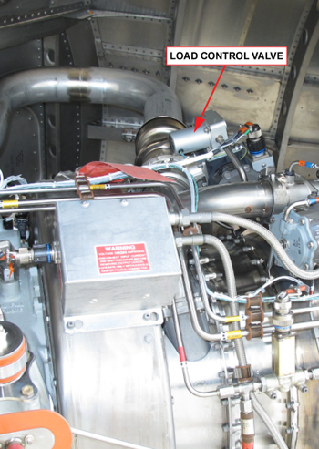
The RE220 can deliver pneumatic power in the form of bleed air from its compressor. The load control valve (LCV) controls the pneumatic load.
When this valve is opened, a portion of the compressor discharge air can be directed from the compressor plenum chamber to either the main engine starter or the environmental control system. The load control valve opens when the cockpit APU BLEED switch (on the BLEED/AIR COND panel overhead) is placed in the OPEN position, or in certain cases, the AUTO position.
The engine reaction to bleed air loads is different from its response to shaft loading. Bleed air extraction from the APU diverts pneumatic energy from the turbine as well as some of the cooling air from the combustion system, the latter causing an EGT rise proportional to the rate of air bleed.
As with a shaft load, the rpm droops, and when the corresponding ECU-commanded fuel flow increases, the RPM is restored to the full governed speed (i.e., 100% rpm), along with a proportional increase in EGT.
Bleed air that is directed into the user systems, via the aircraft ducting, is no longer available to cool the combustion system. This results in a more significant temperature (EGT) increase.
Three variables influence EGT under bleed load conditions:
- Aircraft demand for bleed air
- Outside air temperature (OAT), and
- Air density
Should EGT reach the maximum permissible limit, the ECU will reduce bleed flow by modulating the LCV toward the closed position, to prevent over temperature. When the bleed load demand or the OAT decreases, the ECU will allow the LCV to open only to such an extent which maintains the EGT below the maximum limit.


Gearbox
During the start sequence, the starter motor gear, the compound idler gear, and the high speed pinion engage to turn the rotary group. Together, these gears use the power of the starter motor to increase the speed of the rotary group to approximately 50 percent. Thus when the starter motor gets to approximately 9,000 rpm (and the starter gear/clutch module disengages), the rotary group is at almost 23,000 rpm. After the starter gear/clutch module disengages, the energy from the burned air-fuel mixture increases the engine speed to 100 percent.
During the APU operation, the high speed pinion, the generator compound-idler gear, and the APU generator gear engage. Together, they use the power of the rotary group to supply the specified speed for the APU generator (12,031 rpm). Also, the high speed pinion, the compound idler gear, and the oil pump/fuel control-unit gear engage. Together, these gears use the power of the rotary group to turn the oil pump at its specified speed (6,505 rpm). The oil pump has a gear shaft which engages and turns the fuel control unit.
When the engine is at full speed, the speeds of the primary gears in the gearbox are as shown:
| GEAR NOMENCLATURE | GEAR RPM |
|---|---|
| High Speed Pinion | 45,586 |
| Generator Compound-Idler Gear | 14,527 |
| APU Generator Gear | 12,031 |
| Compound Idler Gear | 12,834 |
| Oil Pump/Fuel Control-Unit Gear | 6,505 |
| Starter Motor Gear | 18,361 |
The gearbox has two primary functions. These functions are to change the output of the:
- Starter motor to the higher speed which is necessary for the power section during the start operation
- Power section to the higher torques and lower speeds which are necessary to turn the accessories
A secondary function of the gearbox is to hold the oil for the oil system.
The gearbox transmits power at the correct rpm between the accessories and the power section. The quill shaft connects the rotary group in the power section to the gears in the gearbox. The gears also connect to the accessories which are attached to the gearbox. During the APU start sequence, the gears change the low-speed high-torque power of the starter motor to be the high speed which is necessary for the rotary group. During APU operation, the gears can change the high-speed low-torque power of the rotary group to be the low-speed high-torque power for the APU generator. And at all the times when the rotary group turns, the gears change its high speed to be the lower speed which is necessary to turn the oil pump (and thus the fuel control unit, too).
The housing of the gearbox is a high-strength aluminum housing that holds the gears and bearings, and it is the sump for the oil system. It has a grounding lug, two APU mounts (for mounting struts), and two hoist mount pads. It is connected to the ambient air through the gearbox vent tube. The housing has pads and installation interfaces that follow:
- The starter gear/clutch module
- The filler-neck and cap
- The magnetic drain plug


05/24/16
System Operation
APU Compartment
The APU is mounted in the tail cone by a multi-axis suspension rod system securing it in all axes.
The APU compartment is completely sealed from the atmosphere with the exception of the inlet door and exhaust duct. The APU compartment is isolated from the rest of the airplane for fire protection. The APU is designed for full rotor burst containment.
Cooling of the APU compartment is accomplished by an exhaust eductor system that draws airflow through the oil cooler and across the APU engine. The airflow entering the air inlet splits in two directions. One direction allows air to flow to the inlet plenum (to the compressor), while the other direction allows the air to flow through the oil cooler to provide cooling for the APU oil. The air flowing through the oil cooler then passes through the compartment to cool the APU and its mounted components. This air is then exhausted overboard through an exhaust eductor.
Access to the APU for inspection, maintenance and servicing is provided by two cowl doors located under the APU. These doors are to be kept closed during normal APU operation. However, they may be opened for APU inspection while the APU is running. In such case, to avoid an APU oil over temperature, limit operation with the doors opened to a maximum of:
- 10 minutes with the APU unloaded (no bleeds, no electrics), and/or
- 5 minutes with the APU loaded (bleed air on and a maximum electrical load of 20 kVA)
APU Engine
The APU engine consists of the following:
- Inlet door – Variable position (0 to 45 degrees). The door opening angle, controlled by the FADEC, is a function of weight-on-wheels, airplane Mach number and APU speed
- Compressor – A single stage centrifugal impeller. Delivers approximately 55 psi bleed pressure at normal operating speed
- Reverse flow annular combustor – Contains 10 fuel nozzles and 2 igniters
- Turbine – Two stage axial flow turbine which drives the compressor and the gearbox
- Gearbox – Provides the sump for the lubrication system and mounting of component and accessories
- Exhaust – The flow across the APU and oil cooler is created by the eductor using the exhaust discharge velocity
- Three monitor zones for fire/overheat detection. The FIDEEX monitors the health and status of the system

APU Operating Envelope
On the ground, the APU is capable of providing electrical and bleed air loads. In flight, the APU is capable of supplying electrical loads up to 45,000 feet and can be started up to an altitude of 37,000 feet. Bleed air for main engine starting (MES) and environmental control system (ECS) is available up to 30,000 feet.
Electrical Loads
Electrical loads of up to 40 kVA can be supplied continuously from the APU generator up to an altitude of 30,000 feet without restrictions. 40 kVA can be supplied continuously between 30,001 and 37,000 feet, provided that a minimum of 0.7 Mach airspeed is maintained. Between 37,001 and 45,000 feet, a maximum load of 28.2 kVA (excluding the electrical hydraulic pumps) may be supplied, if a minimum airspeed of 0.7 Mach is maintained.
Bleed Loads
Bleed load requirements up to 87.3 lb/min airflow at a bleed pressure of up to 55.6 psig can be sustained by the APU up to an OAT of 39.9 °C (103 °F) at sea level. Under these conditions, the temperature of the bleed air is 247.8 °C (478 °F) and the APU consumes fuel at a rate of 295 lb/hr.For specific operating procedures and limitations,particularly with regard to priorities of usage during simultaneous demands of both electrical and pneumatic loads in flight/on ground.

