


Overview
The function of the start/ignition system is to accelerate the APU and cause the ignition of the air-fuel mixture in the APU combustion chamber. The start/ignition sequence continues until the APU can accelerate under its own power.
The full authority digital engine controller (FADEC) initiates and controls the start/ignition sequence. Electrical control power for the start/ignition system is supplied by the FADEC. The power supply for the APU starter is from the APU battery direct bus, through an 800 ampere current limiter/fuse located in the APU start contactor assembly.
The functions of the ignition/starting system are to supply:
- Electrical energy to burn the air-fuel mixture
- Mechanical energy to turn the internal components of the APU
These functions occur each time you operate the APU, but only before the engine gets to full speed.
The ignition/starting system operates in a specified sequence of steps to start the APU. This sequence is known as the ignition/start sequence, and it is as follows:
- The FADEC does a pre-start built in test equipment (BITE) check for condition and operation
- The flight compartment display is energized, and gives an EICAS indication of "APU in BITE"
- The FADEC causes the inlet door to open (on the ground, the inlet door opens before the APU starts; in flight, it opens while the APU starts)
- The FADEC energizes the starting system
- The FADEC energizes the ignition system, and at the same time causes the fuel control components to supply fuel
- The FADEC removes the electrical power from the starting system
- The FADEC removes the electrical power from the ignition system
The FADEC does checks before and during the ignition/start sequence. Before the ignition/start sequence can start, the FADEC must satisfactorily complete the pre-start BITE check of the components that are in the airborne auxiliary power system (and also some components that are in related systems). The permitted conditions for a pre-start BITE check for airborne starts are different than for ground starts. During the ignition/start sequence, the FADEC will cause a protective shutdown of the APU if it finds a condition which will prevent satisfactory operation. Some of the conditions which will cause a protective shutdown on the ground will not prevent an airborne start. The APU can start at altitudes up to 37,000 ft (11,280 m).
The APU electrical control system consists of the FADEC, the Start and Ignition Systems, and the Electrical Sensors. The FADEC is designed to establish and maintain precise control of the APU.
The start and ignition systems are utilized by the FADEC to initiate and control the operation of the APU. The electrical sensors are used in conjunction with the FADEC to provide the sensing and control functions required to operate the APU.
Primary and secondary (backup) control power for the APU is supplied via the FADEC. Primary power is from the Battery Bus, via the Secondary Power Distribution Assembly (SPDA 3), while secondary power is from the Avionics Battery Bus via the DC Power Center (DCPC). The power supply for the APU starter is from the APU Battery Direct Bus, through a 800 ampere current limiter/fuse located in the APU Start Contactor Assembly.

Ignition System
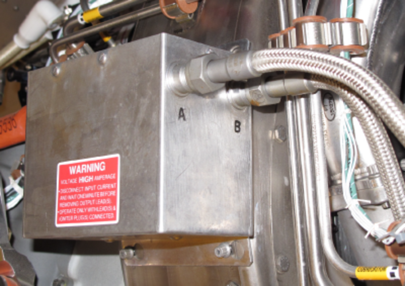
The ignition system consists of a dual output ignition unit, two ignition leads and two igniter plugs. The ignition unit is mounted on the left side of the inlet plenum. The igniter plugs are located at the 2 and 8 o´clock positions on the aft end of the combustor plenum case.
The ignition unit is a dual output, solid state component. It can operate on 10 to 36 VDC input voltage, and produces a maximum output of 3,000 volts. There are two cycles of operation: "Burst" for starting and "Maintenance" for acceleration. Control of the operation of the ignition system is by inputs from the FADEC.
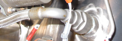
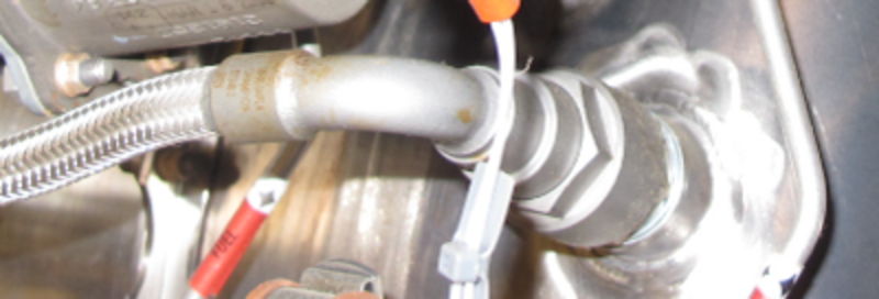
The ignition leads consist of a silicone-insulated, low tension ignition wire covered with a flexible tube of spirally wound nickel-iron alloy and an outer stainless steel braid. Lead connectors are self locking and do not require safety wiring.
Each igniter plug is equipped with a dowel for ease of installation. Igniter plugs are a "drop-in" type, there is an adapter in the combustor plenum case with a seating for each igniter. The adapter also has a mating slot for the dowel on the plug. The igniter is first "dropped" in and positioned to sit in the slot, then the ignition lead is connected to the plug to hold it in place and enable it to function.

All ignition system components are LRUs; maintenance is on an "on-condition" basis.
The FADEC provides a BITE indication for each ignition channel. If the FADEC detects a fault, it is recorded by CAIMS. The FADEC can provide either one of two fault identifiers:
- The ignition unit fails to produce adequate spark energy, or
- A lead or plug fails to deliver sparks due to an open circuit in the ignition system
The function of the ignition system is to cause the air-fuel mixture in the APU combustion chamber to burn during the ignition/start sequence. The full authority digital engine controller (FADEC) uses 28 VDC power from an aircraft battery bus to energize the ignition system during the ignition/start sequence. The ignition system then causes intermittent electrical sparks. These sparks cause the ignition of the air-fuel mixture in the APU combustion chamber.
Ignition Exciter
The ignition exciter changes a low voltage input to a high voltage output. Its usual input voltage is approximately 28 VDC, but it can operate with an input of 10 to 36 VDC. Its usual range of output voltages is 2,000 to 3,000 VDC. The ignition exciter has a specified duty cycle.
The FADEC controls the operation of the ignition exciter. The ignition exciter has two ignition circuits which operate independently. One circuit will continue to supply electricity if the other does not operate. When the ignition exciter is initially energized, its spark rate is 5.5 to 6.5 sparks each second for each circuit. This initial spark rate continues for 5 to 6 seconds. Then its spark rate becomes 1.3 to 1.7 sparks each second for each circuit. This maintenance spark rate continues until the FADEC removes the power. After the FADEC removes the power, the ignition exciter will decrease its output voltage to zero in no more than two minutes. The ignition exciter attaches with bolts to the inlet compressor duct of the APU.
Igniter Plug Lead
There are two igniter plug leads, which are the same but for their length. The igniter plug leads are shielded cables with low electrical resistance. They transmit the output voltage of the ignition exciter to the igniter plugs. Each igniter plug lead has terminals with threads which lock when tightened. These terminals are found on the ignition exciter and on the igniter adapters. When an igniter plug lead is installed on the igniter adapter, it holds its mating igniter plug in position. The longer of the two igniter plug leads attaches with clamps to the bottom of the APU.
Igniter Plug
There are two igniter plugs, and they are installed on opposite sides of the APU. The two igniter plugs are interchangeable. An igniter plug can give a spark when fully soaked with fuel. Each igniter plug is in an igniter adapter. The igniter adapter has a thread and is installed in the combustor case. The APU can start with only one igniter.
Starting System
The FADEC controls the starting system. It energizes the APU start contactor, which lets DC power come from the APU battery direct bus to energize the starting system. The FADEC causes the starting system:
- To start to operate while the APU is at an initial rpm of zero or some other low value
- To continue to operate until it increases the rpm to approximately 50% speed
During the ignition/start sequence, the starting system causes the gearbox to turn the rotary group of the APU. The FADEC removes the power from the starting system when the APU gets to the applicable speed. (The APU speed continues to increase without more mechanical input, because the air-fuel mixture continues to burn and supply energy.) To adjust to the conditions at different altitudes, the FADEC calculates the applicable speed and removes the power from the starting system as follows:
- At 46% speed for starts at altitudes which are less than 8,000 ft (2,440 m)
- At 57% speed for starts at altitudes of 30,000 ft (9,144 m)
- At 60% speed for starts at altitudes which are more than 37,000 ft (11,280 m)
The function of the starting system is to supply mechanical energy to turn the APU rotary group during the ignition/start sequence.
Starter Motor
The starter motor is designed to rotate and accelerate the APU during the start cycle. The starter is mounted on the gearbox by means of a "V" band clamp. The starter drive shaft engages the sprag clutch assembly located inside the gearbox.

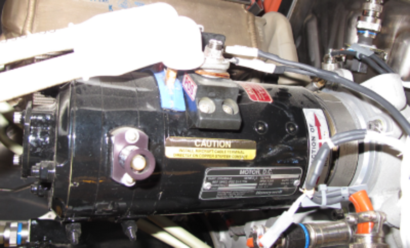
Starter electrical power is provided by the 28 VDC APU Battery Direct Bus. Operation of the starter is automatically controlled through a spring-loaded rotary selector switch marked "OFF-RUN-START" on the overhead APU panel in the cockpit.
When the APU switch on the overhead panel is moved to the momentary START position and released, the FADEC generates a command to engage the starter.
Once the APU has reached a self-sustaining speed, the FADEC will cut out the starter power supply. At this point, the sprag clutch will mechanically decouple the starter from the gear train.
The starter motor has a splined shaft which engages the starter gear/clutch module. When the starter motor operates, it causes the starter gear/clutch module to turn the gear assembly in the gearbox. The coupling clamp attaches the starter motor to the starter adapter.

The starter motor is specified for an output of 5.7 hp (4,250 W) at 16.0 VDC, 500 A, and 5,000 rpm. Maximum current during a start can be as high as 1,400 A. The starter motor supplies an output torque which is equal to or more than the drag of the APU. During operation, the starter motor has properties of operation which change in relation to the altitude and the ambient temperature. These properties of operation are:
- The output torque
- The quantity of current used
- The time of operation
The hand crank mechanism has a protective cover, which is the hand crank access cover. The hand crank mechanism lets you manually motor the engine, which can be necessary during fault isolation procedures. The brush indicator has a button which gives a visual indication of the satisfactory or unsatisfactory condition of the electrical brushes. Thus, it is not necessary to remove the electrical brushes from the starter motor to examine them. The oil seal keeps oil from the gearbox out of the starter motor. If the oil seal has a leak, the oil will drain through the oil seal witness hole in the starter motor.
Starter Gear/Clutch Module
The starter gear/clutch module has a gear, a clutch assembly, and bearings. It is in the gearbox, and the starter adapter attaches to the gearbox with bolts. The starter gear/clutch module engages the gear assembly in the gearbox. The function of the starter gear/clutch module is to transmit the power from the starter motor to the gear assembly during the start sequence. The starter gear/clutch module disengages when the FADEC removes power from the starter motor.
The sprag clutch is mounted in the starter adapter in the accessory gearbox. The sprag clutch assembly bearings and the starter spline drive shaft are lubricated by the APU lubricating system. Both the starter and sprag clutch are LRUs.
The starter has the following design features:
- Visual brush wear indicator
- Non-interchangeable terminals
- Hand crank provision to rotate the gas generator when performing a borescope inspection or to check rotation of the unit for any unusual load and/or noises
- Removal and replacement time is approximately 10 minutes
- Witness drain hole to detect oil seal leakage

The starter is an "on condition" component, requiring no scheduled inspections and no service requirements. Removal of the starter does not require removing any additional components or equipment. The starter brushes are not line replaceable.
04/16/20
System Operation
Starter
Starter operation begins when the APU switch on the overhead panel is momentarily placed in START and released to spring back to the RUN position. The APU FADEC controls the APU starter contactor located in the ASCA. When an APU start is initiated, the contactor coil energizes and APU battery direct bus power is fed to the APU starter through an 800-amp fuse. The start contactor command status is sensed at the ground side of the coil and transmitted to the ACPC.

Starter rotation drives the sprag clutch,rotating the gas generator through the gear train ofthe gearbox. During the start cycle, starter cutout is controlled by the FADEC at various speeds depending on prevailing conditions. At sea level,cutout takes place at 45% rpm. During in-flight starts, starter cutout may occur anywhere from 45% to 60% rpm, as determined by the FADEC.
If the APU rpm is greater than 5% and less than starter cut out rpm for longer than 30 seconds, the APU FADEC will carry out a protective shutdown.
Operation of the starter is automatically controlled by the FADEC, through the APU control switch. Starter operation begins by selecting the START position on the APU control panel. At sea level, starter cutout occurs at 46%. At altitude, starter cutout may be as high as 60% to ensure a positive start. The starter is capable of an immediate restart on roll down when APU rpm is at or below 7% rpm.
Ignition System
The ignition system consists of a dual output ignition unit, two ignition leads and two igniter plugs. There are two cycles of operation: BURST for starting (at 5% for 5 to 6 seconds) and then MAINTENANCE for acceleration (duration of the start).
Ignition system operation is fully automatic and is controlled by the FADEC. At 5% APU rpm, the "Burst" cycle provides 5.5 to 6.5 sparks per second, to both igniters, for 5 to 6 seconds. The "Maintenance" cycle provides a spark rate of 1.3 to 1.7 sparks per second, to both igniters, for the duration of the ignition cycle.
During APU operation in the non-essential mode (i.e. during ground operation), ignition is terminated at 50% APU rpm. In the essential mode (i.e. in-flight), ignition is terminated at 98% rpm. Should an engine flame out occur during operation, the ignition unit will automatically fire the igniter plugs through the "Auto Relight" function of the FADEC.
Troubleshooting consists of a BITE interrogation of the FADEC. However, the FADEC will not log a fault for a mechanical failure, such as a crack in the ceramic, or a center electrode worn beyond limits.
Caution:
The high output current of the ignition unit necessitates precautions be taken to assure that personnel are protected from electrical shock. During ignition system maintenance, the procedures recommended in the maintenance manual should be strictly followed.