


Overview
The function of the indicating system is to make and keep a record of the number of starts and the hours of operation for the APU.
The full authority digital engine controller (FADEC) controls the operation of the indicating system. During the APU prestart check, the FADEC reads the data of the indicating system. The FADEC keeps the values of these data during the APU operation. When the APU gets to 95% speed, the FADEC energizes the indicating system. The indicating system is energized until the APU shutdown occurs.
After the shutdown, the FADEC again reads the data of the indicating system. The FADEC compares its calculated values (for the hours of operation and the number of starts) with the values in the indicating system. If the values from the indicating system do not agree with the FADEC values, the FADEC sends a fault indication to the central aircraft information maintenance system (CAIMS).
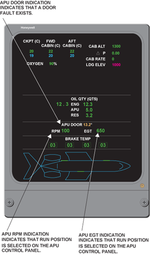
The EICAS STAT page shows APU rpm, EGT, and door position.
05/26/16
Time Totalizing Meter
The time totalizing meter is a small digital counting device that operates with a 28 VDC input, used to track APU operating hours. It is mounted on the APU inlet duct, right hand side (as viewed from the front) just below the P2 pressure sensor. The time totalizing meter attaches with screws to a bracket on the front face of the inlet compressor duct. It has a slot in its flange which aligns with a rivet which is installed in the bracket.

The time totalizing meter is powered to start functioning at 95% rpm and is deactivated when an APU shutdown is initiated. There is no readout on the meter itself, a hand-held reader can be connected to the time totalizing meter to get a digital indication of the hours of operation. The FADEC provides a 28 VDC power source. The time totalizing meter contains its own NVM.
The FADEC provides an excitation signal to the time totalizing meter that activates the internal counter circuitry. The meter is read during pre-start BITE and provides operating hour data via the ARINC data bus.
At the end of each APU run, the FADEC reads and stores the information. On the next start, the information stored is checked and compared with the time totalizing meter reading. If the information is different, the FADEC will update its own clock.
To see operating hours, the FADEC memory can be viewed in the CAIMS system. On the Global Express and Global 5000, wiring provisions allow the APU FADEC to signal an external APU hour meter. The APU hourmeter (if installed) receives the APU FADEC's electrical ready-to-load signal for its operation.
05/26/16
Start Counter Meter
The start counter meter is a solid state meter that operates with a 28 VDC input. It is located on the left rear side of the air inlet duct, just below the P2 and T2 sensors; it is attached with screws to a bracket on the rear face of the inlet compressor duct. It has a slot in its flange which aligns with a rivet which is installed in the bracket. The start counter meter records the number of starts of the APU, each time the APU is started (above 95%); it adds the latest start to the number of starts already in its memory. In the event of a failed start (APU does not reach 95% speed), the start counter is not activated. Prior to shutdown, the FADEC updates its memory to the current number of starts from the start counter. The start counter contains its own NVM. A hand-held reader can be connected to the start counter meter to get a digital indication of the number of starts. If necessary, this information can be downloaded by query via the CAIMS system.
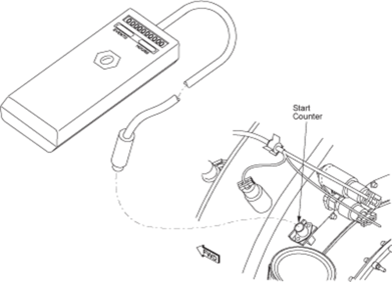
An hour meter/start counter reader may be used to view the APU hours and starts recorded. This tool interfaces directly with the hour meter and start counter installed on the APU.

System Indications
APU Door Indication
The APU door position is normally NOT displayed on the EICAS STAT page. It is only indicated when there is a door fault and will appear in conjunction with an APU DOOR FAIL caution message. When a door fault is sensed by the FADEC, an amber numerical readout in degrees will be displayed.
The start counter meter is a solid state meter that operates with a 28 VDC input. It records the number of starts of the APU. You can connect a hand-held reader to the start counter meter to get a digital indication of the number of starts. The start counter meter attaches with screws to a bracket on the rear face of the inlet compressor duct. It has a slot in its flange which aligns with a rivet which is installed in the bracket.
APU RPM and EGT Indications
For normal operations, two APU parameters (rpm and EGT) are displayed on the status page when the RUN position is selected on the APU control panel. With the APU switch selected to OFF, the display remains active until APU speed drops below 5 percent, and the APU door is closed. The numerical readouts change to red when their limit values are exceeded.
