


Overview
The function of the power plant system is to give support to the auxiliary power unit (APU) and to supply the interfaces for it.
The power plant system includes the APU, and the struts and mounts which hold the APU in the aircraft tail-cone. It also has other systems which are interfaces between the APU, the aircraft, and the ambient air. These interfaces let the APU operate. The interfaces have four general functions:
- To supply the electrical power, the electrical signals, and the electrical protection to the APU
- To supply the ambient air to the APU and remove the compressed air from the APU
- To drain unwanted materials from the APU
- To remove heat from the APU and its systems
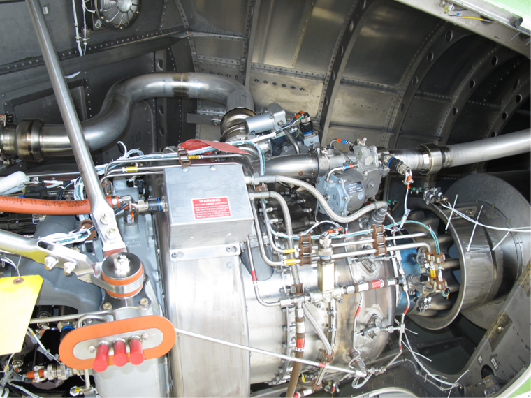
The RE220 APU power plant consists of a single-stage centrifugal compressor, a two-stage axial turbine, an accessory gearbox with an integral oil reservoir, a common shaft to connect the three components above, an annular reverse flow combustor and an exhaust duct and eductor. The power plant is also provided with a monopole and thermocouples to enable measurements of RPM and EGT for display in the cockpit.
The APU installation includes the mount system, the air inlet system, drain system and the bleed and surge ducts. The main rotating group of the engine consists of a single-stage centrifugal flow compressor and a two-stage axial flow turbine on a common shaft, which drives an accessory gearbox. The compressor is compact and equipped with a load control valve (LCV) and a surge control valve. The accessory gearbox drives an AC generator, to power the aircraft electrical buses.
Engine power is developed through compression of ambient air by a centrifugal compressor. The compressed air, when mixed with fuel and ignited in the annular, reverse flow combustor, drives a two-stage axial flow turbine. The rotating shaft power of the turbine rotor drives the compressor, the output drive shaft and the accessories. The APU is suspended by three vertical and two forward suspension rods and is positioned with its gearbox facing forward. The exhaust discharge port is open at the right side, near the aft end of the tail cone.
The APU is provided with an air inlet door, which is operable by an electric actuator as per commands from the full authority digital engine control (FADEC), which may position it to a variety of positions. The APU air inlet and door are located on the top right side of the rear fuselage. The APU and enclosure are equipped with a drain system. Stainless steel lines drain the combustion case and the fuel control unit (FCU) through the APU drain mast. The air inlet plenum has a drain fitting at the 6 o´clock position to drain any water (or fluid) that enters the intake overboard through the tail cone. To eliminate the risk of fluid accumulation, an enclosure drain is provided at the forward side of the APU compartment.
The "Bearing Witness Drain" is a stainless steel pipe routed from a point on the gearbox just above the magnetic chip detector, to the APU drain mast. This drains the compressor bearing seal area and provides the crew with a means to identify a leaking carbon seal at the compressor front bearing.
A bleed air outlet and a supply duct are located on the upper left side of the APU compartment. The duct connects the APU bleed air to the aircraft pneumatic ducting system via the APU load control valve (LCV). A surge control air discharge duct is located on the lower left side of the compartment. It provides an exit port for the APU "surge bleed air" via the APU surge control valve (SCV). The APU SCV opens only in flight above 15,500 feet.


Support Mountings
The function of the auxiliary power unit (APU) support mountings is to hold the APU in the aircraft tail-cone and keep it stable.
The APU is suspended by three vertical and two forward suspension rods, and is positioned with its gearbox facing forward. The exhaust discharge port is open at the right side, near the aft end of the tail cone.
The support mountings are six strut assemblies which attach at three points on the APU. The strut assemblies also attach at five points on the aircraft. Of these aircraft connection points, four are external to the APU compartment and one (the aft strut assembly) attaches to the airframe in the APU compartment. The support mountings hold the APU at a 10 degree nose down attitude.
Mounting Struts
There are four different types of mounting struts. All the mounting struts are made of stainless steel tube. They are as follows:
- Bottom strut assemblies
- Top strut assemblies
- Diagonal strut assembly
- Aft strut assembly
The bottom and top strut assemblies attach to the left side and the right side of the APU at two front connection points. These connection points also have the mounting brackets and the mounting adapters. The mounting adapters attach with bolts, which go into the APU gearbox housing. A long shoulder bolt attaches the mounting brackets to the mounting adapters. The diagonal strut assembly attaches to the right mounting bracket. At the point where the diagonal strut assembly attaches, the right mounting bracket has a bearing which has a spherical movement.
The aft strut assembly attaches to the top rear of the APU. At the point where the aft strut assembly attaches, the mounting bracket has a bearing which has a spherical movement. The top of the aft strut assembly attaches to a bracket on an aircraft structural channel at the top of the APU compartment.
The aft strut assembly is the only strut assembly which attaches to the aircraft at a point which is in the APU compartment. All of the other strut assemblies attach to aircraft brackets which are external to the APU compartment. The strut assemblies attach with bolts and lock-nuts at all of the points which are in the APU compartment. At the points which are external to the APU compartment, the strut assemblies attach to the aircraft with bolts, nuts and cotter pins.

05/24/16
Electrical Harness
The function of the electrical harness is to transmit electrical power and signals between the aircraft and the equipment that follows:
- The auxiliary power unit (APU)
- The full authority digital engine controller (FADEC)
The engine branched wiring harness connects the APU and most of its electrical and electronic components. It connects to the aircraft circuits through a connector on the APU/aircraft tail-cone firewall. Most of the electrical power and signals that go between the aircraft and the APU go through the FADEC. The only component of the APU which does not have an interface through the electrical harness is the oil sump heater. The connector components of the electrical harness are different to prevent installation in an incorrect location.
Engine Branched Wiring Harness
The engine branched wiring harness has many wires which connect to electrical connectors and terminal lugs. It has two terminal lugs (which attach to the APU starter motor) and 19 electrical connectors. These electrical connectors connect to 18 electrical or electronic components on the APU. The other electrical connector connects to the aircraft circuits through a connector on the APU/aircraft tail-cone firewall. There are many clips which hold the engine branched wiring harness in position. These clips are at different locations along the engine branched wiring harness. Grommets are installed between the clips and the engine branched wiring harness to prevent damage to the engine branched wiring harness.


05/24/16
Air Inlet Door System
The function of the air inlet door system is to supply ambient air to the air inlet ducting for auxiliary power unit (APU) operation.
The air inlet door system opens to supply ambient air to the APU, and closes when air is not necessary. The full authority digital engine controller (FADEC) controls the operation of this system. To do this, the FADEC receives signals from the aircraft and the APU. The FADEC receives signals that gives the condition of the ambient air. It uses these inputs to calculate signals which control the operation of the air inlet door system. The FADEC also uses feedback from a component of the air inlet door system to know the position of the inlet door. Power from the APU battery direct bus, through the FADEC, energizes the electrical/electronic components of the air inlet door system.
The adjustment of the air inlet door system is done through the FADEC and the central aircraft information management system (CAIMS). The air inlet door system includes the indications and adjustments that follow:
- Visual indication (the position of the inlet door)
- Electrical/electronic indication (the position signal from the inlet door rotary transducer)
- Mechanical adjustment (the adjustment screw on the linear actuator)
APU Air Inlet Door and Air Inlet
The inlet door is a rectangular sheet metal assembly. It attaches to a hinge between the inlet door and the inlet duct rear section. The right hinge arm (which moves when the inlet door moves), engages the shaft of the inlet door rotary transducer. The actuator arm engages the linear actuator rod. The actuator arm supplies the mechanical connection to open and close the inlet door. The location of the inlet door is on the top external skin of the tail-cone (FS1093.50), near the top center.
The APU is provided with an air inlet door, which is operable by an electric actuator as per commands from the FADEC, which may position it to a variety of positions. When the APU is running, suction created at the air inlet by the APU compressor as well as an "eductor" in the exhaust, causes atmospheric air to be drawn through an air inlet duct. It splits into two separate branches to flow respectively into the compressor plenum, and the APU compartment. The first branch supplies combustion and cooling air to the APU engine, while the second routes the rest of the air through the APU's oil cooler. This latter air is drawn through the eductor to join the exhaust stream for discharge overboard. The APU air inlet and door are located on the top right side of the rear fuselage. The light alloy inlet ducting includes flexible portions, which cater to possible relative motion between its component parts during APU operation.
The door is rectangular and hinged at the rear, with the leading edge sticking into the airstream when open to any degree, thus allowing air to enter the air inlet. In the closed position, the door outer skin is flush with the fuselage skin and the air inlet is tightly closed to prevent wind milling a non-operating APU engine.
On the ground, the door is opened fully for both start and run operations. In flight, the door is initially positioned (as per schedules of the FADEC) to various positions until startup, and to full open position for operation. It is closed at the end of the APU shutdown cycle, when the APU rotation is below 25% rpm.
APU Inlet Door Positions
APU Inlet Door Positions shows the various positions to which the FADEC moves the APU inlet door under a variety of Airspeeds and APU speeds.
The inlet door rigging function is interfaced with the central aircraft information maintenance system (CAIMS), which, when accessed as applicable, will assist the maintenance crew by providing a series of instructions for rigging the APU door properly.
APU Inlet Door Failure Indication
The inlet door position is indicated on the status page only if the door position does not agree with the FADEC's command.On such occasions, the number of degrees of door opening appears as an amber digital readout next toa white label marked APU DOOR. An "APU DOOR FAIL" CAS message would also be shownon the primary EICAS display).
APU Door-related Dispatch Limitations
If the APU inlet door has failed open:
- The APU door can be closed manually (on the ground), or
- The APU must be operated continuously in flight, or
- The APU must not be allowed to windmill between 4 to 30% rpm, otherwise APU engine may incur damage due to insufficient lubrication
Linear Actuator
The linear actuator operates with electrical power. Its actuation rod connects to the actuator arm. When the linear actuator is energized, the actuation rod extends to cause the inlet door to open. When the linear actuator is de-energized, the actuation rod retracts to cause the inlet door to close.
The electrical power to operate the linear actuator comes from the APU battery direct bus. The signals to energize or de-energize the linear actuator come from the FADEC. The electrical power and the control signals come through the connector (at the APU/aircraft tail-cone firewall), which connects to the connector for the inlet door control harness. When in non essential mode, the FADEC energizes the linear actuator when you turn the APU rotary switch (in the flight compartment) to the RUN position. When in essential mode, the FADEC energizes the linear actuator when you turn the APU rotary switch to the START position.
The linear actuator attaches to a bracket on an aircraft channel. Its location is very near the top of the APU tail-cone compartment, on the left side of the inlet duct rear section.

Inlet Door Rotary Transducer
The inlet door rotary transducer is a rotary variable differential transformer. It uses electrical power from the FADEC for its operation, and transmits feedback signals to the FADEC that are related to the inlet door position. The inlet door rotary transducer has a circular shaft with a flat side that engages in the right hinge arm. When the right hinge arm moves with the inlet door, the shaft of the inlet door rotary transducer turns and thus causes the feedback signals. The FADEC uses these feedback signals for adjustment of the inlet door position, and to cause the door position display in the flight compartment. The inlet door rotary transducer is a small component that has a cylindrical shape. It has a cable with an electrical connector which connects to the inlet door control harness. It attaches to the right bearing housing assembly, a related component of the inlet door. Its location is very near the top of the APU tail-cone compartment, on the right side of the inlet duct rear section.


Air Inlet Ducting
The function of the air inlet ducting system is to supply ambient air to some auxiliary power unit (APU) systems and the APU tail-cone compartment.
The air inlet duct system divides the inlet air into two different flow paths. One flow path moves 80 percent of the air to the APU inlet (which has a foreign object damage/icing screen) and the other 20 percent to the APU oil cooler. The air inlet duct system has stainless steel ducts and flexible multi layer glass reinforced silicone rubber sections.
Inlet Duct Forward Section
The inlet duct forward section is a stainless steel duct which connects the inlet compressor duct (through the inlet duct boot) to the inlet door (through the inlet duct rear section). This supplies the ambient air to the APU. The inlet duct forward section attaches to the inlet duct boot and the inlet duct rear section with bolts. A bonding electrical jumper makes an electrical bond between the inlet duct forward section and the inlet duct rear section.
Inlet Duct Boot
The inlet duct boot is made of flexible, multi layer glass reinforced silicone rubber. It is installed between the inlet duct forward section and the APU inlet compressor duct. It attaches to the inlet duct forward section with bolts and to the inlet compressor duct with clips.
Oil Cooler Duct
The oil cooler duct is a stainless steel duct which connects the air/oil cooler (through the oil cooler duct boot) to the inlet door (through the inlet duct rear section). This supplies the ambient air which removes heat from the APU and from the APU oil. The oil cooler duct attaches to the oil cooler duct boot and the inlet duct rear section with bolts. A bonding electrical jumper makes an electrical bond between the oil cooler duct and the inlet duct rear section.
Oil Cooler Duct Boot
The oil cooler duct boot is made of flexible, multi-layer glass-reinforced silicone rubber. It is installed between the oil cooler duct and the air/oil cooler. It attaches to the oil cooler duct with bolts and to the air/oil cooler with clips.


05/24/16
Bleed Air Ducting
A bleed air outlet and a supply duct are located on the upper left side of the APU compartment. The duct connects the APU bleed air to the aircraft pneumatic ducting system via the APU LCV (Load Control Valve)
The function of the bleed air ducting system is to transmit compressed air from the APU to the aircraft pneumatic system.
The bleed air ducting system connects the bleed air supply system on the APU to the pneumatic ducting system of the aircraft. It transmits the compressed air from the APU compression section for use in the aircraft bleed air systems.
Bleed Air Duct
The bleed air duct is a stainless steel tube which has three curves. It is installed on the front of the APU, on the top left side. One end is attached with a coupling to the APU bleed air check valve and the load control valve. When the load control valve is open, the bleed air duct transmits the compressed air from the APU to the firewall fitting assembly. The other end is attached with a coupling to the firewall fitting assembly. Each end of the bleed air duct has a flexible joint.

Surge Venting
The function of the surge venting system is to move unwanted compressed air from the APU to the ambient air. The surge venting system connects the compressor control system on the APU to the ambient air. It moves the unwanted compressed air from the APU compression section to a fitting on the aircraft skin.
A surge control air discharge duct is located on the lower left side of the compartment. It provides an exit port for the APU surge bleed air via the APU SCV (Surge Control Valve). The APU SCV opens only in flight above 15,500 feet.
Surge Duct
The surge duct is a stainless steel tube with two flexible joints and one curve. It is installed near the bottom left side, at the rear of the APU. It is attached to the APU surge valve and to the surge fitting assembly with couplings. When the surge valve is open, the surge duct moves the unwanted compressed air from the APU to the surge fitting assembly.


Draining
The function of the draining system is to remove small quantities of unwanted fluids from the auxiliary power unit (APU) systems.
The draining system drains unwanted fluids (oil, fuel, water) from the APU to the ambient air. These fluids can collect in different components of the oil, fuel and engine systems of the APU. The draining system releases these collected fluids through two openings in the APU access doors. There is a tube in one of these openings which drains water and contamination from the bottom of the inlet compressor duct. Installed there are three tubes in the other opening which drain the fluids that follow:
- A mixture of oil and fuel from a leak at the shaft seals in the fuel control unit of the APU
- Oil from a leak at the oil seal near the compressor bearing which is in the power section of the APU
- Fuel (that is not burned) from the combustor case which is a component of the power section
APU Drain System
The APU and enclosure are equipped with a drain system comprising the following:
- Intake Plenum Drain
- Compressor oil witness drain
- Combustion Case
- Fuel Control Unit Drain
- Enclosure Drain
The air inlet plenum has a drain fitting at the 6 o’clock position. Any water (or fluid) that mayenter the air intake drains overboard through the intake plenum drain tube.
The oil compressor witness drain is routed from the gearbox to the APU drain mast. This drains the compressor bearing seal area and provides a means to identify a leaking carbon seal at the compressor front bearing.
Small quantities of hot compressed air continuously leak from the plenum case through the combustion case drain. The combustion case drain is a fitting with a very small orifice. Any fuel collected in the combustor case after an aborted start is also drained overboard through this orifice drain.
The fuel control unit has a witness drain for fuel or oil that might leak from the fuel control/oil pump spline area.
An enclosure drain at the forward side of the APU compartment eliminates the risk of fluid accumulation. Any water or fluid that may enter the air intake drains overboard through the tail cone.
Drain Bracket
The drain bracket is installed with bolts on the bottom front left of the APU gearbox. It has the drain mast seal which engages against a bracket/opening on the APU access door. The drain mast seal prevents an air leak from the APU compartment. The drain bracket has three short tubes which extend through the APU access door and which engage the bottom ends of the tubes that follow:
- The fuel control drain tube which has its top end connected to the seal witness opening on the fuel control unit
- The oil witness drain tube which has its top end connected to the oil transfer tube
- The turbine case drain tube which has its top end attached to the orifice fitting assembly
The drain bracket also supplies a stable surface for the connection between the oil refill hose assembly and the remote oil fill tube


Eductor System
The function of the eductor system is to remove heat from the APU and from its oil.
The eductor system has no components, but it uses some of the components from other systems to cause its operation. These components are as follows:
- Inlet door
- Oil cooler duct
- Oil cooler duct boot
- Air/Oil cooler
- Turbine bearing support
- Bell mouth of the exhaust tailpipe duct
- Exhaust tailpipe duct
- APU compartment
When the aircraft is on the ground, and the APU operates, the APU exhaust goes out quickly through the exhaust tailpipe duct. The exhaust gas movement through the clearance between the turbine bearing support and the bell mouth of the exhaust tailpipe duct causes a venturi. The venturi pulls air out of the APU compartment to cause a low pressure in the compartment. Low pressure then pulls ambient air through the air inlet ducting system, then through the APU air/oil cooler. Here, heat is removed from the oil system.
After the ambient air goes through the air/oil cooler, it continues around the external surfaces of the APU. This removes heat from the APU. The air then goes out of the APU compartment through the clearance between the turbine bearing support and the bell mouth. Here the ambient air is mixed with the exhaust gases as they go out of the aircraft, through the exhaust tailpipe duct.
When the aircraft is in flight, and the APU is in operation, air is pushed into the inlet ducting through the open inlet door. This supplies sufficient quantity of ambient air for the air/oil cooler and to cool the APU. The air then goes out of the APU compartment through the clearance between the turbine bearing support and the bell mouth.


09/25/20
Component Location Index
| Component Location Index | |||
|---|---|---|---|
| IDENT | DESCRIPTION | LOCATION | IPC REF |
| - | MOUNTING STRUTS | ZONE(S) 320 | 49-11-01 [ GX ] [ GXRS ] [ G5000 ] |
| - | ENGINE BRANCHED WIRING-HARNESS | ZONE(S) 320 | 49-12-01 [ GX ] [ GXRS ] [ G5000 ] |
| - | BLEED AIR DUCT | ZONE(S) 320 | 49-16-01 [ GX ] [ GXRS ] [ G5000 ] |
| - | SURGE DUCT | ZONE(S) 320 | 49-17-01 [ GX ] [ GXRS ] [ G5000 ] |
| - | DRAIN BRACKET | ZONE(S) 320 | 49-18-01 [ GX ] [ GXRS ] [ G5000 ] |