


05/24/16
Overview
The passenger door is the usual entrance and exit point for the passengers and crew. The passenger door is on the left side of the forward fuselage between FS310+32.00 and FS347+32.00 for Global 5000 and between FS310 and FS347 for Global Express/XRS. The passenger door is a plug-type door which has airstairs attached to the inner side. The passenger door and air stairs (which open out and down), turn on two hinges attached to the airstairs and the hinge points on the fuselage. The door contains the lock shaft, internal and external handles, and a residual pressure relief flap. The door rises up out of the airframe abutments on levers attached to the airstairs as the lock handle is moved to the unlocked position. Handrails are attached to each side of the airstairs and the fuselage. The handrails extend and retract as the passenger door opens and closes.
The passenger door is made from alloy skins, doublers, machined frames, and diaphragms. A depressurization vent flap is installed in the top half of the passenger door.
A disk spring damper is installed on the passenger door latch mechanism. The disk spring damper holds the latch mechanism in the fully open or fully closed position when moved over-center. Negative G-locks and negative G-lock cams are installed on the latch mechanism. The negative G-lock cam mechanism moves the passenger door in relation to the airstairs, which turns on the fuselage hinges. The latch mechanism is operated by internal or external handles. A magnetic sensor is installed as provision for an optional security system.


Passenger Door Latch Mechanism
Initial movement of the latch mechanism opens the depressurization vent flap in the top half of the passenger door. The vent flap is pulled by a wire rope assembly and is held open by four extension springs. Initial movement also operates negative G-locks to release the passenger door from the airstairs.
Continuous movement causes the passenger door to move in and up to be clear of the junctions in the passenger door frame. The torque tube engages on a latch to keep the position of the passenger door in relation to the airstairs.
The internal or external handle turns the torque tube when it is lowered. The negative G-lock cams on the torque tube release the negative G-locks which then move as a result of the negative G-lock spring force. The negative G-locks engage when the passenger door is found behind the junctions. If a negative G-lock spring failure occurs, secondary negative G-lock cams move the negative G-locks in position.
The depressurization vent flap is pushed closed by a roller arm. Four extension springs hold the vent flap in the closed position.


11/14/16
Passenger Door Internal Handle
The internal handle is a lever installed on the forward side of the passenger door. The handle is attached to the torque tube and the forward lift arm. The lift arm lifts the passenger door in relation to the airstairs when the handle is moved out of the locked position.
A disk spring damper applies a load to prevent accidental operation of the handle, when it is in the closed position. The disk spring damper assembly on the latch mechanism moves into an over-center position as the torque tube moves to the fully locked or fully open position. A negative G-lock spring holds the handle in the locked position. The negative G-lock spring helps to lift the passenger door when the handle is moved out of the locked position. The negative G-lock spring also decreases the force on the handle. Stop buttons attached to a lever on the torque tube keep to a limit the turn of the handle. The airstairs and handrails also protect the handle from accidental operation.
A/C pre SB700-52-022 have a green indicator in the handle cover that indicates when the door is locked.
A/C post SB700-52-022 have red alignment marks on handle cover that line up with a red mark on the handle when the door is locked.


Passenger Door External Handle
The external handle is in the structure in the lower half of the passenger door. Levers and control rods connect the handle to the forward lift arm.
The disk spring damper assembly on the latch mechanism moves into an over-center position as the torque tube moves to the fully locked or fully open position. A negative G-lock spring holds the handle in the locked position. When the handle is moved out of the locked position, the negative G-lock spring helps to lift the passenger door. The negative G-lock spring also decreases the force on the handle. Stop buttons attached to a lever on the torque tube keep to a limit the turn of the handle.


05/24/16
Passenger Door Internal Switch
The internal switch (identified DOOR) is installed at the passenger door opening on the frame at FS295 for Global Express/XRS and at FS295+32.00 for Global 5000 in the passenger compartment. The switch is used to close the passenger door with electrical power. When you operate the internal switch for two seconds, electrical power is provided to the passenger door for 30 seconds and the door will close.

Passenger Door External Switch
The external switch is installed in the fuselage, aft of the passenger door, behind an access panel. The switch is used to close the passenger door with electrical power. When you operate the external switch, the passenger door will close. The external switch must beheld until the passenger door closes.

Passenger Door Handrails
The handrails are made from alloy tubes, which extend as the passenger door opens. A handrail is attached to each side of the airstairs and the passenger door frame. The passenger door frame attachment points are also used as cable quadrant attachments for a counterbalance tensator spring in the airstairs. The tensator spring gives more power to the actuator to retract the passenger door. The handrails engage in a handrail hook retainer on each side of the airstairs when they are fully extended. This makes the handrails stable.
The handrails hold the weight of the passengers on the airstairs, when the passenger door fully extends.

01/30/15
Passenger Door Actuator
The actuator is installed adjacent to the middle shaft in the airstairs. The actuator turns the middle shaft with a single row chain and sprockets, to close the passenger door. The passenger door actuator is operated by a switch in the passenger compartment or an external switch, aft of the passenger door.
The actuator and the tensator springs give the torque to lift the passenger door to the closed position. The actuator uses a brushless DC motor which is connected to a planetary gearbox and slip clutch and to the output shaft. The motor is energized during the door close sequence which takes 18 seconds maximum (30 seconds maximum with SB700-52-037 or SB700-1A11-52-014 incorporated).
The proximity switch (internal of the actuator circuit card) energizes a slowdown circuit. This decreases shaft rotation before the door reaches the locked close position.
When the door is opened and the motor is not energized, an eddy current damper controls the speed. The door opening time is 7.0/8.5 seconds (10 seconds maximum).
Before full open, the proximity switch energizes the slowdown circuit, which decreases the shaft rotation speed before the door is fully opened. The slip clutch prevents the output shaft from being overdriven. A thermal switch is attached to the motor to remove voltage if the motor becomes too hot.
The six main components contained in the actuator are:
- a dc motor with no brushes
- an eddy current damper
- a slipping clutch
- an output gearbox
- a position sensor mechanism, and
- an electronic control card

Passenger Actuator Door Chain
A single row chain engages with a sprocket on the actuator shaft and on the torque shaft. The chain transmits torque from the actuator to the torque shaft, to help the tensator springs lift the passenger door. The chain also turns the actuator as the passenger door opens, the actuator makes an eddy current damper effect in the actuator, to help slow the rate of fall.

Passenger Door Airstairs
The airstairs have a structure made of a composite material of honeycomb covered with carbon fiber and glass cloth. There are six fixed steps and two steps which fold. One of the steps which fold is found at the top and the other at the bottom of the airstairs. Two hinges made from alloy attach the airstairs to the aircraft structure.
The top step makes the airstairs flush with the passenger cabin floor. A continuous hinge attaches the top step to the top fixed step of the airstairs structure. The top step folds under the airstairs when the passenger door closes and opens.
The bottom step opens outboard as the passenger door opens and folds inboard as it closes. Two hinges made from alloy attach the airstairs to the aircraft structure.
Lift arms attach the passenger door to the airstairs at the top end. The lift arms are part of the lock roller shaft on the lock mechanism. The bottom end of the passenger door engages on spigots and cams on the airstairs.


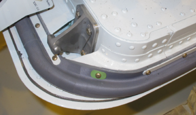
Passenger Door Seal
A rubber retainer seal is attached with bolts around the edge of the passenger door. The seal is made stronger with a fabric. The seal contains a secondary movable seal which prevents fast decrease of pressure if the primary seal becomes damaged.

Passenger Door Tensator Spring
The four tensator springs are found on the inner aft face of the airstairs. The tensator springs are made of steel and measure over 15 ft (4.57 m) in length when fully extended.
The tensator springs are pulled from their natural curve around four tensator drums, when the passenger door opens, to an opposite curve on one torque drum. This makes an almost constant spring force on the outer rim of the torque drum and thus in the torque shaft. The torque will hold most of the weight of the passenger door as the torque shaft turns and the passenger door opens or closes.
Passenger Door Disk Spring Damper
The disk spring damper is part of the mechanism between the internal and external handles. The disk spring damper moves into an over-center position as the handles go to the fully locked position. The handles are then held with the spring pot to prevent accidental operation. The spring load also helps to lift the passenger door and reduce the load on the handles when they are moved to the open position.


Passenger Door Cable
The forward and aft cables are attached to cable clamp quadrants on the passenger door opening structure and pulleys on the torque shaft. When the passenger door is open and the actuator is started, the torque shaft turns the pulleys. The cables are then wound around the pulleys and the passenger door is lifted. The cable lengths are adjustable at the cable clamp quadrants to make sure that they have equal tension.


Vent Flap
On door closure, pressurization of the aircraft is prevented by the installation of a vent flap in the door structure unless the door is correctly closed and locked.
The flap is held open by four tension springs and is driven shut by a cam face on the aft G-latch via a series of levers during the final locking sequence.
The design is such that only two springs are required to retain the vent flap in the open position.
In the event of residual cabin pressure or icing conditions, during door deployment, the vent flap is pulled open by a direct link to the torque tube prior to full door lift, via a cable assembly.

Passenger Door Top Step
The top step makes the airstairs flush with the passenger cabin floor. A continuous hinge attaches the top step to the top fixed step of the airstairs structure. The top step folds under the airstairs when the passenger door closes and opens.


Passenger Door Bottom Step
The bottom step opens outboard as the passenger door opens and folds inboard as it closes. A link and drive arm mechanism on theforward handrail moves the bottom step.

Passenger Door Proximity Sensors
There are three proximity sensors installed in the passenger door. Two are located inside the airstairs and sense "G" lock position. The third senses the outer handle position.
The proximity sensors provides indication to the crew via EICAS displaying a caution "Passenger Door" (amber) when the door is not properly locked.
The sensors confirm that the G-latches have fully engaged on the airstairs pin when the door is fully locked and the external handle is closed.
This electrical indication system defaults to fail safe (i.e. caution "Passenger Door") when a sensor or interface electronics fails.
The proximity sensors are monitored by the LGECU (landing gear electronic control unit). There is also a mechanical indication pointer to indicate that the door is locked.

System Operation
Door Opening
When the internal or external lock handles are moved from the locked position they rotate the lock shaft which opens the vent flap and then releases the ´G´ locks. Further rotation of the lock handle causes the door to move slightly inboard, then up, disengaging from the frame abutments. This lifting motion is created by leverage on links connected to the airstairs and assisted by a spring pot connected to the lock shaft. When the door has been fully lifted and the lock shaft has reached its full rotational travel position a latch engages into the lock shaft at its aft end to hold the door in its correct position in relation to the airstairs while the door is open and down.
Door Closing
The lock shaft latch is released when the door is returned to the up position by a trip lever contacting a striker on the door frame. This allows the lock handle to lower the door into the frame abutments, engage the ´G´ locks and close the vent flap. If the door handle is unlocked, and then the operator wishes to lock it again without fully opening the door, the lock shaft latch release mechanism must be reset by moving the door partly out and then pulling it back in and then moving the handle to the locked position.
Manual Closing
A rope wound round a pulley on the aft end of the torque shaft must be unwound sufficiently to be brought up into the cabin. The rope can be pulled, rotating the torque shaft and raising the door via the normal cables. The rope pulley is much larger than the cable pulleys thereby reducing the pulling force necessary. Once the door is raised it may be lowered into the frame and locked by the normal method with the lock handle.

10/16/20
Component Location Index
| Component Location Index | |||
|---|---|---|---|
| IDENT | DESCRIPTION | LOCATION | IPC REF |
| - | PASSENGER DOOR LATCH-MECHANISM | ZONE(S) 832 | 52-11-01 [ GX ] [ GXRS ] [ G5000 ] |
| - | PASSENGER DOOR INTERNAL-HANDLE | ZONE(S) 832 | 52-11-05 [ GX ] [ GXRS ] [ G5000 ] |
| S32/S21 | PASSENGER DOOR INTERNAL-SWITCH | ZONE(S) 832 | 52-11-09 [ GX ] [ GXRS ] [ G5000 ] |
| - | PASSENGER DOOR EXTERNAL-HANDLE | ZONE(S) 832 | 52-11-13 [ GX ] [ GXRS ] [ G5000 ] |
| S31/S105 | PASSENGER DOOR EXTERNAL-SWITCH | ZONE(S) 832 | 52-11-17 [ GX ] [ GXRS ] [ G5000 ] |
| - | PASSENGER DOOR HANDRAILS | ZONE(S) 832 | 52-11-21 [ GX ] [ GXRS ] [ G5000 ] |
| B45 | PASSENGER DOOR ACTUATOR | ZONE(S) 832 | 52-11-25 [ GX ] [ GXRS ] [ G5000 ] |
| - | PASSENGER DOOR AIRSTAIRS | ZONE(S) 832 | 52-11-29 [ GX ] [ GXRS ] [ G5000 ] |
| - | PASSENGER DOOR CHAIN | ZONE(S) 832 | 52-11-33 [ GX ] [ GXRS ] [ G5000 ] |
| - | PASSENGER DOOR SEAL | ZONE(S) 832 | 52-11-37 [ GX ] [ GXRS ] [ G5000 ] |
| - | PASSENGER DOOR TENSATOR-SPRING | ZONE(S) 832 | 52-11-41 [ GX ] [ GXRS ] [ G5000 ] |
| - | PASSENGER-DOOR DISK-SPRING DAMPER | ZONE(S) 832 | 52-11-45 [ GX ] [ GXRS ] [ G5000 ] |
| - | PASSENGER DOOR CABLE | ZONE(S) 832 | 52-11-49 [ GX ] [ GXRS ] [ G5000 ] |
| - | PASSENGER DOOR TOP-STEP | ZONE(S) 832 | 52-11-53 [ GX ] [ GXRS ] [ G5000 ] |
| - | PASSENGER DOOR BOTTOM-STEP | ZONE(S) 832 | 52-11-57 [ GX ] [ GXRS ] [ G5000 ] |
| MT42/MT43/MT44 | PASSENGER DOOR PROXIMITY-SENSOR | ZONE(S) 832 | 52-70-01 [ GX ] [ GXRS ] [ G5000 ] |