


05/27/16
Overview
The cowling components attach together around the engine to make a nacelle. The function of the nacelle is to divide the airflow around the engine. The nacelle is designed to house the engine in a smooth casing and to keep drag as low as possible. The airflow that goes through the inlet cowl divides into the engine compressor and the fan bypass duct. The external surface of the nacelle makes an aerodynamic surface to give a smooth airflow around the engine. An overview of the components which make up the nacelle, including an outline of the propulsion unit.
They are either right-handed or left-handed and are not interchangeable.
The nacelle outer surface carbon fiber composite (CFC) parts have a pre-impregnated copper mesh. This lamination is used to shield the electronic system against high intensity radiated field (HIRF) interference during lightning strikes.
The cowling components are parts of a very strong but low-weight assembly which gives the engine protection.


Access Panels and Doors
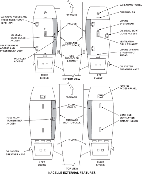
The power plant system consists of the access panels and doors, the air inlet (or nose) cowl, the fixed cowl, the upper and lower cowl doors, the engine mounts and the exhaust unit.
The panels and doors provide access to various system components for maintenance, allow ventilation air in, and enable accumulated air/gas and fluids to exhaust overboard. The position of most of the panels and doors is determined to a great extent by the position of the system components on the engine.
The air inlet cowl allows passage of all the air required by the engine with minimum pressure loss and a uniform distribution of pressure across the face of the fan, and assists in minimizing nacelle drag.
The fixed cowl acts as an infill panel and as a continuation of the nacelle external surface between the pylon and the upper and lower cowl doors. The fixed cowl is also the support for the cowl doors. All engine to aircraft system interfaces pass through the fixed cowl within the pylon footprint.
The cowl doors form the outside surface of the nacelle between the intake cowl and thrust reverser unit. They provide access and ventilation to the accessory gearbox and fan and bypass duct.
The exhaust unit provides a continuation of the nacelle exterior aerodynamics at its outer surfaces. While at its internal surfaces, it acts as a collector for exhaust gases discharged by the engine, with the rear end of the unit acting as a propelling nozzle.
Note:
There are seals all around the cowl. The front and rear seals are attached to the inlet cowl and exhaust unit. The top and bottom edge seals are attached to the fixed cowl. There is also a continuous seal between this cowl and the pylon.
05/27/16
Inlet Cowl
The inlet cowl is at the forward part of the engine and has four main structural parts (the primary assembly, the intake barrel assembly, the aft bulkhead and the outer skins) and a thermal anti-icing (TAI) system.
The primary assembly is made of an aluminum alloy lipskin and a titanium forward bulkhead. The lipskin contains a TAI spray ring which is made of titanium and is attached to the forward bulkhead.
The air inlet cowl allows passage of all the air required by the engine with minimum pressure loss and a uniform distribution of pressure across the face of the fan, and assists in minimizing nacelle drag.
The air inlet cowl is fixed to the front flange of the engine fan case module by bolts; two locating dowels fixed to the intake cowl flange ensure correct orientation. Each inlet cowl is made for the left/right engine position and is not interchangeable between them.
The air inlet cowl is made up of four major structural elements as follows:
- A titanium bulkhead which supports a titanium thermal anti-ice (TAI) spray ring and an all metal primary assembly formed by a light alloy lipskin
- An inner barrel consisting of two acoustically treated "NOMEX" segments and a light alloy nose cowl attachment ring
- An outer skin assembly consisting of two Carbon Fiber Composite/CFC segments and a light alloy panel for gaining access to the P20 and T20 probes (discussed later)
- A rear bulkhead assembly consisting of two CFC segments joined at the top and bottom center by titanium plates. The titanium straps also form the recesses for the TAI duct at the bottom and for P20/T20 probe connections at the top
The intake barrel assembly is made of two carbon-fiber composite (CFC) sound-attenuation panels. These panels are connected longitudinally and are attached at the aft end to an aluminum alloy ring. This ring attaches the inlet cowl to the engine-fan-case forward flange.
The aft bulkhead is made of two CFC pieces connected by titanium straps. The aft bulkhead makes the forward firewall of the engine accessory zone. It also gives a mating surface for the upper and lower cowls at its outer edge.
The outer skins are made of two CFC panels with stiffeners and an aluminum alloy panel which holds the TAI system outlet-grille. The TAI system uses hot air which goes through the ducts from the 5th stage engine offtake. The hot air increases the temperature of the internal surface of the lipskin. The supply and exhaust duct goes through the aft bulkhead and into the TAI spray ring. Subsequently, the air goes overboard through a grille in the outer skin of the inlet cowl.
The inlet cowl is not interchangeable between the left and right engines.
Notes:
- The nose cowl inner barrel and lipskin should be protected against accidental damage. During maintenance, the use of a work mat is recommended
- If the fan module is to be removed, the intake cowl has to be removed first


05/27/16
Upper Cowl
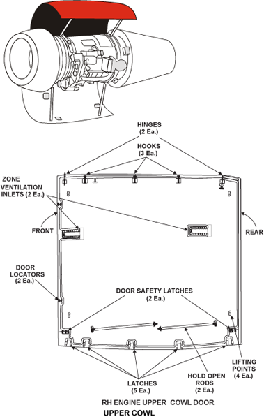
The cowl doors form the outside surface of the nacelle between the intake cowl and thrust reverser unit. They provide access to all the gearbox, fan and bypass case mounted accessories and systems.
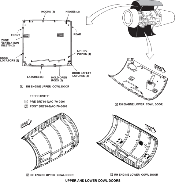
The upper cowl is made from CFC and gives protection to the upper half of the engine. The cowl doors are attached on the inboard side to the fixed cowl by two hinges and three hooks (for each door). On the outboard side, the doors abut each other and are fastened together by five latches. The doors are left- or right-handed and not interchangeable. Door restraint latches on the forward and aft edges of the upper cowl make sure that it cannot open accidentally when the lower cowl is open.
The upper door has, at the top dead center position, two ram air intakes (for zone 1 ventilation and cooling). The front edge has two door locators. When the door is closed, the locators fit into receptacles on the rear seal of the inlet cowl and ensure correct alignment when closed.
The rate at which the upper cowl opens and closes is controlled by two damper struts. The upper cowl is held open by two struts which are attached to its inner surface.
Two additional latches are provided (fore and aft) to keep the upper door closed in windy conditions while the lower door is being opened. Two hold open rods are provided which must be used to support the door in the open position.
The inner surface of the upper cowl also contains two “Y” shaped ventilation inlet ducts. These ducts are made of titanium and they let external air flow over the engine.


05/27/16
Lower Cowl
The lower cowl is made from CFC and gives protection to the lower half of the engine. It is installed between the aft edge of the inlet cowl and the forward edge of the thrust reverser. The lower cowl is held closed by five latches installed along the mating faces of the lower and upper cowls. It turns on two hinges and three forks attached to the fixed cowl.
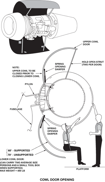
The rate at which the lower cowl opens and closes is controlled by two damper struts. The lower cowl is held open by two struts which are attached to its inner surface.
There is a door locator on the forward edge of the lower cowl. As the lower cowl is closed, the door locator engages with a receptacle on the inlet cowl. This makes sure that the lower cowl is aligned correctly.
The lower cowl door has access points to these items:
- The drains mast
- Zone 1 ventilation exhaust grill
- Starter air valve access and pressure-relief door
- CAI control valve access and pressure-relief door
- Provided on the left installation is an access panel for the oil level sight glass; on the right engine installation, an access panel is provided in this area with quick-release fasteners
The lower cowl access doors for the TAI valve and the starter air valve will blow out if the pressure in the nacelle becomes too high. On the left cowl only, there is an access door for the gearbox oil sight glass.
The lower cowl contains a stainless steel drains dish, which lets unwanted engine fuel and oil drain overboard. There is also an air outlet grille, which is made from aluminum honeycomb.
The lower cowl is not interchangeable between the left and right engines.
Notes:
- Both cowl doors must be supported by the front and rear hold open rods when opened
- The lower door can be used as a seat to aid working on the lower inboard area of the engine (maximum weight allowed on this door is 450 pounds)
- The gearbox as well as the fan case and bypass duct mounted accessories can be accessed by opening both cowl doors
- Maximum wind speed limit to open the cowl doors is 52 knots (60 mph)
- Supported, the door will open to a maximum of 60 degrees
- Unsupported, maximum opening 75 degrees
Post SB-BR710-NAC-70-0001 (9214 and Subs)
The cowls are single cure monolithic design. The composite facing sheet is supported by a series of hoop stiffeners laid over a Rohacell foam core. The cowl also gives fire and high intensity radio frequency (HIRF) protection.


05/27/16
Fixed Cowl
The fixed cowl acts as an ´infill´ panel and as a continuation of the nacelle external surface between the pylon and the upper and lower cowl doors. The fixed cowl is also the support for the cowl doors.
The fixed cowl is made from super-plastically formed titanium and is on the inboard side of the engine, between the upper and lower cowls.
The fixed cowl touches the engine pylon, and is attached at its forward edge to the inlet cowl by shear attachment brackets and bolts. At its aft edge, the fixed cowl is attached to the thrust reverser forward bulkhead by shear pins.
The fixed cowl abuts the outboard face of the pylon. The front end of the fixed cowl is secured in position by shear-type attachment brackets and bolts which attach it to the intake cowl. At the rear, it is secured by attached shear pins which fit snugly into brackets attached to the exhaust unit front bulkhead. The fixed cowl is either left-/right-handed and is not interchangeable between left and right engines.
The fixed cowl is either left-/right-handed and is not interchangeable between left and right engines. The fixed cowl is a special type of one piece titanium structure and provides a firewall between the engine and the aircraft pylon.
All engine to aircraft system interfaces pass through the fixed cowl within the pylon footprint.
There are seals all around the cowl. The front and rear seals are attached to the inlet cowl and exhaust unit. The upper and lower edge seals are attached to the fixed cowl. There is also a continuous seal between this cowl and the pylon.
The upper and lower edges of the fixed cowl each have two hinges and three hooks which hold the upper and lower cowls. The forward and aft engine mounts, the thrust strut and different engine and aircraft systems go from the engine to the aircraft through the fixed cowl.
The forward engine mount is contained in a titanium firebox which is attached to the inner surface of the fixed cowl. The thrust strut and aft engine mount go through fireproof silicon rubber boots which are attached to the fixed cowl. The bleed air duct, the pre-cooler air duct and the main generator cables also go through fireproof seals on the fixed cowl.
There is one panel for the fuel, remote oil fill and fire extinguishing bulkhead connectors. There are separate panels for the electrical and hydraulic bulkhead connectors. A fire detection rail and its electrical harness are also installed. On the right fixed cowl only, there is an access door for the gearbox oil sight glass. The fixed cowl is not interchangeable between the left and right engines.


Exhaust Unit
The exhaust unit provides a continuation of the nacelle exterior aerodynamics at its outer surfaces. At its internal surfaces, it acts as a collector for exhaust gases discharged by the engine, with the rear end of the unit acting as a propelling nozzle.
The exhaust unit is bolted to the rear flange of the structural bypass duct module. The fixed structure and reverser door inner surfaces are constructed from noise attenuating material. The oil system breather pipe passes through the exhaust unit and discharges overboard on the outboard side of the engine.
It should be noted that for installation or removal of this unit during the buildup or dismantling of a power plant, all attachment items which require access are positioned on the top, bottom and outboard side of the unit, except for the inboard primary thrust reverser lock mechanism.

09/15/20
Component Location Index
| Component Location Index | |||
|---|---|---|---|
| IDENT | DESCRIPTION | LOCATION | IPC REF |
| - | INLET COWL | ZONE(S) 400 | 71-11-02 [ GX ] [ GXRS ] [ G5000 ] |
| - | UPPER COWL | ZONE(S) 400 | 71-12-01 [ GX ] [ GXRS ] [ G5000 ] 71-12-02 [ GX ] [ GXRS ] [ G5000 ] |
| - | LOWER COWL | ZONE(S) 400 | 71-13-01 [ GX ] [ GXRS ] [ G5000 ] 71-13-02 [ GX ] [ GXRS ] [ G5000 ] |
| - | FIXED COWL | ZONE(S) 400 | 71-14-01 [ GX ] [ GXRS ] [ G5000 ] |