Overview
The function of the electrical harnesses is to transmit the electrical signals which control and monitor the engine. The harnesses are the interface between the engine system components, the engine electronic controller (EEC) and the aircraft. They also send data to the engine indicating and crew alerting system (EICAS) in the flight compartment.
An electrical harness is an assembly of cables. Cord ties installed at specified distances hold the cables together. These distances are proportional to the diameter of the cable assembly. There are cord ties also where the harness divides into cables which connect to their related components. Clips hold each loom in position on the engine. These clips attach to tube lugs, brackets or raceways as applicable.
There are two or three cables wound together (looms) in a jacket. The jackets are screened and fire resistant. Pins or sockets, which are crimped on the ends, are installed in the electrical connectors. Pins and sockets have different dimensions and are identified by a color code adjacent to the crimped end.
There are three primary groups of electrical harnesses. Most of the looms on the bypass duct connect components/systems to the EEC. The routing of these is around and along the bypass duct to one end or the other of the EEC. There are two looms from the core and the routing of these is through the interservices sealing plate. They then each connect with a loom on the bypass duct which goes to a different channel of the EEC. The other looms are part of the general services harness and are applicable for a left or right engine installation.
All the electrical harnesses that transmit signals to and from the aircraft, have a routing to the fixed cowl. An electrical panel on the fixed cowl has connectors which interface with the electrical harnesses in the aircraft pylon.
Bypass Section Harnesses
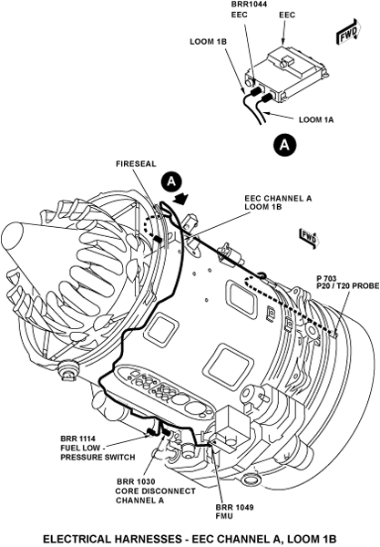
The engine is electronically controlled by a full-authority digital engine-controller (FADEC) of which the EEC is the primary component. There are six primary bypass section harnesses which connect to the EEC, three to each channel. These harnesses transmit signals between the EEC and the FADEC components. Looms 1A, 1B and 1C connect to channel A, and looms 1D, 1E and 1F connect to channel B. The looms, 1C and 1F, which transmit signals between the EEC and the aircraft, are applicable for left and right engine installation.
The routing of looms 1A and 1B is around and along the right side of the bypass duct. These looms go through the right side of the EEC to the rear EEC electrical connectors. The routing of looms 1D and 1E is around and along the left side of the bypass duct. These looms go through the left side of the EEC to the front EEC electrical connectors.
The looms 1C and 1F go through the ends of the EEC trough to the remaining two connectors. Loom 1C goes through the rear to the channel A connector and loom 1F goes through the front to the channel B connector. The routing of these looms is around the inboard side of the bypass duct to the connectors at the apron/pylon interface.


Core Engine Harnesses
There are two core engine harnesses which transmit signals between core components and each channel of the EEC. Loom 2A goes to channel A of the EEC and loom 2B goes to channel B. Each loom includes cables from the components of the FADEC system, and also from the core-engine fire-detection sensors. The routing of the looms is to the interservices sealing plate, where each loom goes through a transition tube. At the interservices sealing-plate connection, there are fire seals on the cables in the transition tubes.
On the other side of the interservices sealing plate, each loom divides and the cables for the core-engine fire-detection sensors go to different points. The other loom assemblies from the core connect to their related bypass section harness to go to the EEC. Loom 2A connects to loom 1B to go to channel A of the EEC. Loom 2B connects to loom 1E to go to channel B of the EEC.


Engine Build-Up (EBU) Harnesses
All the EBU harnesses are applicable for a left or right engine installation. The EBU harnesses contain the general service harnesses and connect them to the fixed cowl/pylon interface. There are two general service harnesses on each engine. Looms 4C and 4D are on the left engine and looms 4L and 4M are on the right engine. These looms transmit signals directly between the components and the aircraft.
The EBU harnesses also include two looms on each engine for the control of the variable frequency generators (VFG). The routing of these looms is on the two sides of the engine and they connect to the fixed cowl/pylon interface. Looms 4G and 4H are on the left engine and looms 4J and 4K are on the right engine. Power supply harnesses transmit 3-phase electrical power from the two VFGs through the fixed cowl to the aircraft electrical system.
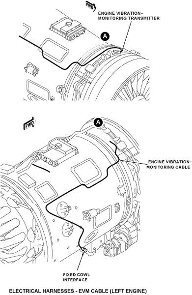
Other components have looms which go independently to the fixed cowl/pylon interface. The routing of the anti-vibration monitoring cable is from the transmitter, around the bypass duct and down the inboard side. The thrust reverser loom goes down the inboard side of the bypass duct at the rear. The thrust reverser loom for the left engine is 4F and for the right engine 4N. The inlet cowl, cowl doors and the fixed cowl, also have harnesses. These attach to the related part of the cowls.