


05/27/16
Overview
The function of the engine drains system is to collect and dispose of any unwanted fluids and to provide a readily recognizable indication of any LRU seal failure. The system also discards fluid leakage from engine units, or fluids that collect in the cowls or fairings.
There are two types of drains as described below:
- Wet Drains: Fluid loss does not necessarily mean a seal failure, i.e., the bypass drain. In inclement weather, it is normal to see water draining, provided the engine is not running. However, if the fluid is fuel or oil, with or without the engine running, it could indicate a problem.
There are two wet drain outlets: drain tank overflow, combined interservices fairing and bypass case drain - Dry drains: All the other drains are designated as dry drains. A fluid loss may indicate the failure of a fuel or oil pipe within the core area. It requires maintenance action before the airplane is released for flight
The engine drains system has many tubes that connect to specified components of the fuel, oil and hydraulic systems. The tubes are connected to the components with bolts or a nut and nipple connection. These tubes which let fluid leakage from applicable components move to a drain point. There are two drain points in the bottom of the engine nacelle to remove unwanted fluid.
The tubes go to overboard exits at the drains mast, or the drains openings at the rear. The forward drain point is a drains mast. The drains mast is forward of the accessory gearbox, at the bottom of the engine. The rear drains openings are at the rear of the lower cowl, at the bottom of the engine.
The other drain point is a mounting plate which is attached at the bottom rear flange of the bypass duct. There is also a fuel drains tank to collect fuel which the engine has not burned. This fuel goes into the tank during engine shutdown.
There are seven drain openings at the drains mast. These are all dry drains. The components that use the drains mast are as follows:
- The fuel pumps
- The fuel-manifold splitter unit
- The fuel metering unit (FMU)
- The two main generators
- The engine-driven pump
- The air turbine starter
There are four drains openings at the rear of the engine. Two openings are wet drains and two are dry drains. These are as follows:
- The drains tank ejector (wet drain)
- The services fairing/bypass duct (wet drain)
- The air-cooled oil-cooler control-valve and actuator (dry drain)
- The variable stator-vane actuator (dry drain)
The drains tank has the capacity to hold the fuel from unsatisfactory starts. The fuel from a subsequent unsatisfactory start would flow overboard trough the wet drain. During a usual engine start an ejector in the drain tank supplies fuel back to the inlet side of the LP fuel pump.


Front Dry Drains Mast
This mast is attached by brackets to the front face of the accessory gear box and groups together a number of drain pipes at a common point, thereby enabling easy identification of the source of any leakage.
The drains mast consists of a flat plate with short drain tubes welded into it, the tubes having disconnect points just above the plate. There is a compressible seal ring around the rim of the plate. Engravings on the bottom surface identify the source of each drain tube.
The lower cowl door incorporates a shallow collector dish with a single exit hole discharging overboard through the cowl. The compressible seal of the drains mast seals against this dish.
Any leakage from the unit drains will drain through the collector dish drain hole, when the lower cowl door is closed. The source of the leakage can be identified by opening the lower cowl door and inspecting the drains mast.
As an example, the hydraulic pump drain marked HYD PUMP is connected to the space between the gearbox and the pump. Engine oil leakage from this cavity indicates a problem with the gearbox seal, whereas leakage of hydraulic fluid down the same drain indicates the failure of the hydraulic pump. The table below lists the LRUs and their type of drains:
| LRU with Cavity Drain | LRU with Case Drain |
|---|---|
| Variable frequency generators 1 and 2 | Overspeed and splitter unit |
| Hydraulic pump | Fuel metering unit |
| Air starter | |
| Fuel pump |

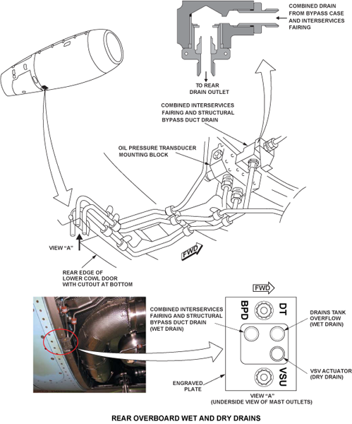
Rear Wet and Dry Drains Outlet
This outlet groups a number of drains to a common point to allow easy troubleshooting for leaks. The outlet is mounted on a bracket attached at its front end to the rear support ring, and at its rear end, to the exhaust unit front bulkhead. The drain exit is at the bottom of the engine at the rear edge of the lower cowl door.
There are three drains at the rear, consisting of plain tubes directed downwards and overboard, the tube ends protruding slightly below the cowl door surface. The three drains that exit at the bottom of the lower cowl door are a combination of dry and wet drains as follows:
- Dry Drain - Variable Stator Vane Actuator
- Wet Drain - Drain Tanks Overflow
- Combined Structural Bypass Duct and Inter-services Fairing
Any leakage from these can be traced back to source by opening the lower cowl door.
Note:
At the time of compiling this Training Guide, there exists in this group of pipes, a redundant fourth tube (which used to be the case drain from an Air Cooled Oil Cooler/ACOC, which is now obsolete) with its end crimped closed. This tube is likely to be removed by Service Bulletin action, presumably in a short time.
Drains Tank
The drains tank has a supply tube and an exit tube. The supply and exit tubes each have two bolts that connect them to the top of the tank. Each tube connection has a packing.
The supply tube comes from the fuel metering unit (FMU). The exit tube connects to an internal tube. The internal tube goes approximately one third in the depth of the tank. When the tank has the maximum fuel in it, the exit tube lets unwanted fuel go overboard through the rear drain opening. The tank is a cylindrical shape and is at the bottom of the engine on the rear flange of the bypass duct. Three brackets are used to safety the tank.

Drains Tank Ejector
The drains tank ejector valve is at the bottom of the drains tank. It has two fuel tube connections. The fuel tubes move the low pressure (LP) fuel flow to the ejector pump. The ejector has a non-return valve and a float valve. When LP fuel flows through the ejector pump, the pressure in the tank becomes more than in the ejector pump. This lets fuel to be removed from the tank and sent back with the LP fuel supply to the pump.
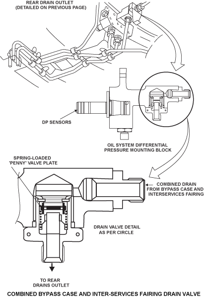
Combined Inter-services Fairing and Structural Bypass Case Drain Valve
This drain valve is attached to the oil pressure transducer mounting block, which is mounted near the bottom of the engine rear support ring and allows drainage of the fluid when it is not running, and prevents loss of bypass air when it is running. The valve consists of a plate valve supported by a light spring assembled into the lower connector union.
System Operation
Any leakage from the unit drains will drain through the collector dish drain hole, when the lower cowl door is closed. The source of the leakage can be identified by opening the lower cowl door and inspecting the drains mast.
When the engine is not running, the spring will keep the valve open; this allows any fluid that is collected in the bypass case and/or the inter-services fairing, to drain overboard. When the engine is running, the bypass air pressure will force the valve to close, thereby preventing any air loss. Any fluid collected in the two areas above, will be blown overboard, along with the exhaust gases.
Note:
In rainy weather, any water leakage from this drain is normal, provided the engine is not running. Such leakage could be minimized or precluded by fitting on the intake and exhaust blanks.
Note:
However, any leak at this drain must be examined, since a zone 2 (or engine core area) fuel pipe rupture will eventually appear as a leak at this point.

09/16/20
Component Location Index
| Component Location Index | |||
|---|---|---|---|
| IDENT | DESCRIPTION | LOCATION | EMM REF |
| - | DRAINS TANK | ZONE(S) 430/440 | 71-71-01 |
| - | DRAINS TANK EJECTOR | ZONE(S) 430/440 | 71-71-02 |