05/27/16
Overview
The power plant is installed on the airframe with engine mounts which are on the inboard side of the engine. Two beams, namely the front and rear mounting beams are used to mount the engine to the airframe. Both of these beams are attached to corresponding hard attachment points on the pylon. A top link and a bottom link on each of the engine mounting beams is attached to the engine.
The front engine mount beam incorporates a center thrust trunnion to bear the weight at the front of the engine as well as the thrust of the engine. A "Thrust Strut" is attached at a point adjacent to the rear face of the center thrust trunnion.
The front mount carries approximately half of the weight of engine and transmits engine thrust loads to the thrust strut, which in turn, transmits them to the airframe. The rear mount holds the remaining weight of the engine. The rear beam supports the engine weight at the rear, and allows axial expansion and contraction at the rear due to temperature transients. The front mount is protected by a firebox, which is also attached to the fixed cowl.

Front Mount
The front mount includes a thrust trunnion, thrust strut, engine-to-airframe links and a front mount beam. The thrust trunnion and thrust strut transmit the engine thrust to the aircraft. The engine-to-airframe links and front mount beam hold part of the weight of the engine.
The bearing housing keeps the spherical bearing of the thrust trunnion in position on the intermediate compressor case. The spherical bearing is free to move in the bearing housing. This lets the engine expand when it gets hot. The spherical bearing has a sliding fit with the aircraft trunnion pin. A castellated nut holds the aircraft trunnion pin in position in the front mount beam.
The front end of the thrust strut attaches to the rear face of the front mount beam. Its aft end attaches to an airframe hard point.
The engine-to-airframe links are installed between the engine intermediate compressor case and the front mount beam, one above and one below the thrust trunnion. The links attach to the intermediate case with bolts. The front-mount beam assembly attaches to the airframe hard point with two pins.
The two locations for the front mount are on the left and right side of the engine intermediate compressor-case. This lets the engine be installed on the left or the right side of the aircraft. A blanking plate gives protection to the thrust trunnion location that is not in use. There are blanking pins on the engine-to-airframe link locations that are not in use.

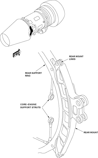
Rear Mount
The rear mount includes two rear mount links and a rear mount beam. These hold approximately half the weight of the engine.
The two rear mount links are installed to the rear support ring. The rear support ring attaches internally to the eight core-engine support-struts. There are locations for the rear mount links, on the left and right side of the engine. This lets the engine be installed on the left side or the right side of the aircraft.
The rear support ring connects to the rear mount beam with two rear mount links. One link is connected to the top of the mount beam, and one to the bottom.