


Overview
The function of the accessory drives system is to change part of the energy of the engine for use by the accessory gearbox. There are drive pads on the accessory gearbox for the engine accessory units.
The internal gearbox supplies the energy to operate the accessories. The internal gearbox transmits the energy from the high pressure (HP) compressor shaft to the radial drive shaft. The radial drive shaft transmits the energy to the accessory gearbox. The gear shaft assemblies in the accessory gearbox transmit the energy to the accessories.
The accessory drives system, through the accessory gearbox, transmits power from the air starter to the HP compressor during normal start procedures. It also has a connection to turn the engine by hand during maintenance operations.

05/30/16
Accessory Gearbox Assembly
The accessory gearbox assembly is located at the bottom of the intermediate case. It is attached by two links (left and right). The right link is a rigid link and the left link is a movable link. This lets different metals in the engine and the accessory gearbox expand in their properties.
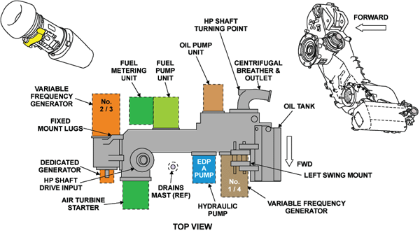
The Accessory Gearbox (AGB) transmits the driving force from the engine to the accessories mounted on the AGB through bevel gears. There are two gearshaft assemblies, one on each side of the bevel gears, where spur gears are used. The gearshaft assemblies transmit the energy to the accessory units installed on the drive pads. The AGB also transmits power from the air starter to the engine during start/crank procedures. In addition, the AGB houses the integral oil tank which contains the engine centrifugal breather, and provides a means of hand turning the engine HP system for maintenance operations. Two standards of AGB are approved for the BR710 engine. The baseline AGB has a cast magnesium housing. An aluminum accessory gearbox is introduced, starting at A/C 9251. The AGB is bolted at the 6 o´clock position of the intermediate module via two brackets, and is driven by the radial drive shaft and it transmits power between the internal gearbox and the accessory gearbox. An AGB magnetic chip detector is located at the center of the AGB rear face.
The AGB drives the following units:
- Variable frequency generators (2 ea.)
- Air Turbine Starter
- Fuel pump and fuel metering unit
- Oil pump unit
- Hydraulic Pump
- Dedicated Generator
- Oil breather (internal)
The rear of the centrifugal breather gear shaft has a connection to turn the HP compressor by hand. Access to this connection is through a plate on the rear face of the oil breather outlet.
The accessory gearbox also has these interfaces:
- Engine vent to breather
- Oil tank vent to breather
- Oil supply connection from engine to oil system
- Dry unit drains (starter, VF generators, hydraulic pump and fuel pump)
- Air supply for the air blown seals
- Oil scavenge connection
- Breather overboard tube
- Anti-suction line
- Rear-bearing chamber scavenge-line
Internal Gearbox
The internal gearbox is contained in the engine front-bearing chamber which is located in the intermediate case. The internal gearbox has two bevel gears. One is attached to the front of the No.3 bearing assembly, the other is the radial drive-shaft bevel gear.
Radial Drive Shaft
The radial drive shaft has external splines at the two ends. One end of the radial drive shaft is located in the internal gearbox bevel-gear. The other end is located into the bevel gear pinion in the spigot of the accessory gearbox assembly.