


Overview
The function of the combustion section is to add fuel to the compressed air and burn it. This gives heat energy to the airflow which turns the turbines.
The combustion chamber mixes the high pressure (HP) compressor air with fuel from the fuel nozzles. Ignition occurs, and this fuel/air mixture burns in the combustion chamber. The increase in temperature causes the gases to expand and accelerate to the rear through the turbines. The turbines change this energy to mechanical energy to turn the compressors and engine accessories.

Outer Combustion Case
The outer combustion case is a one-piece cylindrical structure with flanges at the open ends. The 20 fuel-nozzle bosses are at equal intervals around the case, adjacent to the forward flange. Each boss has holes with threads for the bolts that attach the fuel nozzle. The igniter plug bosses are at the 5 o'clock and 8 o'clock positions, aft of the fuel nozzle bosses. Each of the igniter plug bosses has three holes with threads for the bolts that attach the igniter plugs.
The bosses for the T30 thermocouples are at the 3 o´clock and 9 o´clock positions. Each of the thermocouple bosses has three holes with threads for the bolts that attach the thermocouples. Bosses for P30 air connections are adjacent to the forward flange, at the 11 o'clock and 1 o´clock positions.
The front flange of the combustion outer case attaches to the rear flange of the HP-compressor outer case with bolts. The rear flange of the combustion outer case attaches to the front flange of the HP-turbine outer case with bolts.

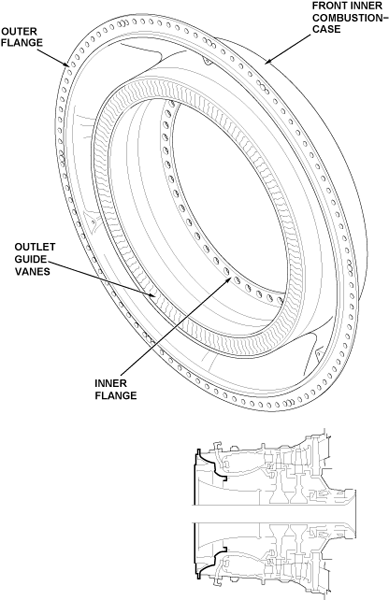
Front Inner Combustion Case
The front inner combustion case is a one-piece structure which includes the HP-compressor outlet guide-vanes (OGVs). The front inner combustion case has a flange on the inner diameter and a flange on the outer diameter. The outer flange is between the forward flange of the outer combustion case and the rear flange of the HP compressor case. It attaches with bolts. The inner flange attaches to the front flange of the rear inner combustion case with bolts.
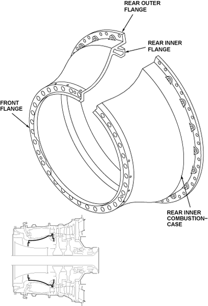
Rear Inner Combustion Case
The rear inner combustion case is a one-piece structure. The case has a flange at the forward edge and two flanges at the rear. The forward flange attaches to the inner flange of the front inner combustion case with bolts. The rear inner flange attaches to the stage 1 pre-swirl nozzle assembly with bolts. The rim seal ring assembly attaches to the rear outer flange of the rear inner combustion case with bolts.
05/27/16
Combustion Chamber
The combustion chamber is an annular structure which has inner and outer surfaces and a curved section at the front end. The inner and outer surfaces have rows of small air holes. The curved section has 20 circular openings for the fuel nozzles. Fuel spray nozzles and igniter plugs installed on the outer case go in the combustion chamber. In the combustion chamber, fuel from the spray nozzles mixes with the air from the HP compressor. Ignition of this mixture occurs. It burns, which gives heat energy to the gases. The combustion chamber has a flange on the rear edge of the outer surface. This flange attaches between the outer case rear flange and the forward flange of the HP turbine case with bolts. On the outer surface, at the 5 o'clock and 8 o´clock positions, are holes for the igniter plugs. The combustion chamber is in the annular space between the combustion outer case and the combustion inner case.
