05/30/16
Overview
The function of the fuel controlling system is to control the operation of the engine in all ground/flight conditions.
Engine fuel controlling is done by the full-authority digital engine-control (FADEC) system. The FADEC system gives all the engine control functions that are necessary. The FADEC system operates with the applicable aircraft or engine sub-systems.
The EEC sets the thrust and makes sure that specified engine parameters stay in safe limits. There are many electrical interfaces between the EEC, the engine components and the aircraft. These are used to control and monitor the operation of the engine and to transmit data to and from the flight compartment.
05/31/16
Full Authority Digital Engine Control (FADEC) System
The function of the FADEC system is to give full control of the engine safely, in all conditions. It is a two channel system and each system can control the engine independently. The primary unit in the FADEC system is the engine electronic controller (EEC). The EEC gives an interface between the aircraft and the engine. The EEC sends inputs to the fuel metering unit (FMU) which does the primary control of the fuel system.
The FADEC system has units and sub-systems which together have full control of the engine operation. The system includes electronic and mechanical units and uses air, fuel and electrical sub-system data for control functions. These are supplied as electrical signals which are sent to the computers. A continuous analysis of the data compares the inputs with engine/system performance and automatically adjusts the fuel flow or air flow as necessary. During usual engine operation, a dedicated generator energizes the FADEC system.
The primary unit in the FADEC system is the engine electronic controller (EEC). Signals from the airframe, flight compartment and engine sensors go to the EEC, and output signals transmit instructions to units. One of these signals controls a valve in the fuel metering unit (FMU) to increase or decrease fuel flow. The FMU also supplies pressurized fuel to operate the variable stator vane (VSV) actuator for compressor airflow control. The EEC sends important data to the engine indicating and crew alerting system (EICAS) display in the flight compartment.
The FADEC system also controls the engine start procedure and the thrust reverser system. The FADEC system controls the components in the engine start system, to let the engine start automatically or manually and to relight in flight. When the thrust reverser is operated on the ground, the engine power is controlled in safe limits. The FADEC system also has a data entry plug which sets important maximum limits of engine performance. This plug, which is a part of the engine, connects to the EEC.
The FADEC system controls the engine through its whole operation, from startup to shutdown, including reverse thrust. It also protects the engine from excessive rotor speed.
The FADEC system consists of the following subsystems:
- Electronic engine controller (EEC) dual channels A and B
- Data entry plug (DEP)
- Dedicated generator
- Independent overspeed protection (IOP) system for both N1 and N2
- Fuel metering unit (FMU)
- Fuel pumping system – low and high pressure
- Engine handling bleed valves, controlling HP5 and HP8 stage handling bleeds
- HP compressor control, controlling variable inlet guide vanes (VIGV) and first three stages of variable stator vanes (VSV)
- Starter air valve (SAV)
- Igniters and ignition control units
- Throttle rotary variable differential transformer (RVDT) interface
- Control of thrust reverser
- Associated transducers for engine control and monitoring
- Engine inlet P20/T20 probe
At the heart of the FADEC system is the electronic engine controller (EEC) which interfaces with the applicable aircraft systems to perform the following functions:
Metering of fuel via the fuel metering unit (FMU) to provide total control of:
- Automatic start and relight capability
- Idle speed control
- Engine power setting
- Acceleration and deceleration
- Limit protection for N1 and N2 speeds
- Limit protection for P30 pressure
- Limit protection for T46 temperature (ITT)
- Independent overspeed protection of N1 and N2 systems
Control of compressor airflow via the variable stator vane and HP compressor handling bleed valve systems to ensure:
- Surge free acceleration and deceleration
- Surge recovery
- Stable operation under all conditions
- Control of the igniters and start air valve to enable automatic and manual start and relight capability
- Control of system electrical supply, either aircraft 28 VDC or dedicated generator output, to the EEC internally and through the EEC to the FADEC system
- Control of some of the thrust reverser system functions including control of engine speed in reverse thrust
Note:
Air inlet cowl thermal anti-icing is controlled independently of the FADEC, with the exception of functional links such as igniter control.
Some systems use aircraft power for operation but are switched by the EEC, e.g. igniter power.
The EEC operates on command and information input signals to and from the airframe systems via ARINC 429 bus and, additionally, on analog and digital command and information signal inputs to and from various sensors around the engine. From these inputs, output signals are generated to command various settings of the systems around the engine.
As listed below, the EEC interfaces with various engine systems in different ways depending on the control requirements:
- Electrical systems – via relay switches (usually solid state) to switch electrical power ON or OFF
- Pneumatic systems – via two-position solenoid valves switching an air pressure ON or OFF command
- Hydraulic systems – via two-position solenoid valves switching a hydraulic pressure ON or OFF command (for TRs)
- HP fuel operated systems – via two-position solenoid valves switching an HP fuel pressure ON or OFF command or via electro hydraulic servo valves (EHSVs), using modulated torque motors to vary fuel pressure to control the system
System feedback is either by:
- Engine systems which are modulated, are equipped with linear or rotary variable differential transformers (LVDTs or RVDTs) to indicate precise position over the normal operating range of the system, OR
- In the case of two-position systems (generally controlled by an ON/OFF command), micro switches are used to indicate the most critical position


Engine Electronic Controller (EEC)
The engine electronic controller (EEC) is the controlling unit of the FADEC system. The unit is fitted onto the bypass duct at the 12 o’clock position by four anti vibration mounts, encased in a yellow metal box for fire protection, and protection against high intensity radiated fields (HIRFs). A connection is provided for the data entry plug.
The EEC is an electronic control unit containing two channels, A and B. Each channel consists of a central processor unit (CPU), power supply unit (PSU) and an independent overspeed protection (IOP) unit mounted on application-specific integrated circuit (ASIC) boards. Internal hardware features provide fire protection between the two channels. Each EEC channel has three external electrical recepticles mounted on connector modules. The front three are part of channel B. The rear three are part of channel A. The electrical inputs and outputs go to and from channels A and B through these receptacles.
On top of the EEC there is a pressure transducer module which contains two types of pressure sensor. These measure air pressure inputs from different parts of the engine. Air tubes supply P0, P20, P30 and P50 pressure to connectors on the front of the transducer module. The EEC also houses vibrating cylinder pressure sensors for measurement of P50 and P20, and strain gauge sensors for P30 and P0 (ambient pressure). Internal temperature sensors are also included to provide cold junction temperature signals for ITT, engine overheat and T30 measurement/validation.
P0 gives the pressure altitude which the EEC uses in all control related functions and schedules. The EEC also uses the value of P0 when signals are compared, to make sure the cross-check is correct. The engine pressure ratio (EPR), which gives an indication of thrust, is calculated with the values of P20 and P50. The EEC calculates the ratio of P50 to P20 to give the value of EPR. P30 air pressure is continuously monitored for surge conditions. If the EEC senses a possible compressor surge it will schedule the fuel flow to make the compressor stable.
The PSU controls the power supplies to the whole of the FADEC system, the CPU and the IOP unit of the EEC.
The CPU receives and processes all input signals and calculates the controlling output signals and information output signals, as described later in this section.
The IOP automatically shuts off fuel in the event of N1 or N2 reaching the overspeed trigger values, as discussed later in this section.
Note:
The EEC has no service replaceable internal parts.
The EEC system description includes:
- EEC Power Supply Unit
- EEC Central Processor Unit
- EEC CPU Monitoring
- EEC Watchdog Timer
- EEC Independent Overspeed Protection


EEC Power Supply Unit
Each channel of the EEC also has a power supply unit (PSU) and an independent overspeed protection (IOP) unit. The EEC is normally powered by its own Dedicated Generator (DG) when the engine is running. When the engine is not running, the 28 VDC BATT BUS powers the FADEC.
The PSU rectifies both single-phase and three-phase DG outputs from AC to DC and controls the switch over from the aircraft supply to power supplied by the DG. If the DG power supply fails the PSU will revert back to aircraft power supply to continue operation of the engine.
Single-phase DG power will automatically power the Independent Overspeed Protection (IOP) circuits if the DG power output is greater than aircraft supplied power.
Three-phase DG power is selected for the Central Processor Unit (CPU) in a manner similar to the one described above. However, the aircraft power supply to the CPU is switched over to the DG, by the PSU, when DG output voltage greater than 23.7 volts.
The power supply selection methods described above eliminate any power interrupts at the change-over point. Switchover is smooth and diodes prevent DG power from feeding the aircraft bus.

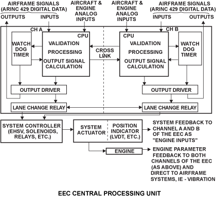
EEC Central Processor Unit
The control functions of the EEC are generated within each channel of the CPU board, with the exception of electrical power supply control and the overspeed protection function.
Channels A and B are mechanically and electrically isolated in the EEC and they operate independently. Each channel gets input and output signals and is independently energized from the power source. The inputs and outputs of one channel cannot have an effect directly on the other channel. But the computers can communicate and compare the data across the channels. Only one channel will be in control of the engine at a time with the other one as an auxiliary channel. An interlock in the circuits prevents control by the two channels at the same time.
Control of the engine automatically alternates between channels for each start, i.e. if channel A is in control, channel B is the backup; on the next start, channel B will control and channel A will be the backup. The change command is triggered by the engine shutdown and recorded in EEC memory (EEPROM) for the next start.
An interlock prevents both channels being in command at the same time. If the controlling channel becomes incapable of control, the lane change relays will switch to the backup channel.
EEC CPU Monitoring
Both lanes of the EEC continuously process input parameters, run their control processes and communicate to the aircraft via ARINC 429 outputs. The most healthy lane of the EEC controls the engine.
There are two types of input signals as follows:
- Duplex - These are signals which are input into both channels A and B
- Simplex - These are singular signals which are either:
- internally cross wired before validation
- internally cross linked during validation
- internally cross-communicated during processing
All input signals are validated, i.e. checked for accuracy. There are three methods of input signal validation as follows:
- Each channel compares its own input signal value against the other channel input signal value
- Each channel checks its input value is within normal engine operating range minimum and maximum values
- Each channel checks an engine parameter value (or to be more precise the signaled value rather than the actual value due to possible sensor output faults) against a synthesized value
Note:
Input signals are validated by one or two of the above methods, not by all three methods. Only the most important signals will be checked against a synthesized value.
Each type of detectable fault is associated with a health level. The health of each lane is continuously monitored and compared. If the lane which is in control develops a fault, and the other lane is healthier, then the control of lane is changed over to the healthier channel. If the lane change operation fails, then the lane which is in control will continue in its function as long as possible. Only the controlling lane is connected to the output.
There are faults which cause loss of function only when present in combination with other faults. Such combinations of fault are assigned an appropriate health level. Health levels lie between full-up functionality and shutdown required.
There is a separate health level scheme, which is to be used if the inter-lane communications fail. The separate scheme allows for parameters which, after their loss, are normally used by the controlling lane across the inter-lane communications. The use of the separate health scheme also indicates to the software that parameter cross checks cannot be performed.
As the control processes are always running, control can be transferred from one lane to the other without delay while the control software is started.
The standby lane, however, outputs default values when it detects that it is not connected to output. The standby lane starts closed loop control of the outputs only after the lane change has been detected.
EEC Watchdog Timer
Both lanes of the EEC have a Watchdog Timer. If the Watchdog Timer senses a CPU malfunction within a time scale then it will impose a CPU reset. In this situation control passes to the other channel temporarily.
A counter is incremented and decremented periodically as control passes temporarily between channels by the CPU. If the counter reaches four CPU resets the Watchdog will impose a freeze and control will pass to the other channel until the fault is rectified and cleared at which point alternating channel control will resume.

EEC Independent Overspeed Protection
The independent overspeed protection (IOP) is a safety function to stop the engine if the compressor speed goes out of limits. The IOP unit of each channel continuously monitors the speed of the LP and HP compressors. Probes, which measure the speed of each compressor shaft, send speed signals. The EEC includes a device which prevents compressor overspeed in usual conditions of operation.
The IOPs will prevent a hazardous overspeed of the N1 and N2 rotors. When either N1 or N2 speed signal has exceeded a preset threshold value, one of the IOPs will vote to close the fuel High Pressure Shutoff Valve (HPSOV), and indicate this to the other channel via a cross link discrete.
Although one channel is in control, both IOPs can function as a result of an overspeed situation. Either channels IOP can sense the overspeed first, and then signal to the other channel. However, the IOP solenoid will not energize unless the other channels IOP circuit also detects an overspeed. Both channels of the IOPs have to agree that an overspeed is occurring before shutting down the engine. An output signal then goes to the FMU and the HP fuel shut-off valve closes to stop the engine.
The overspeed function is checked during normal engine shutdown procedure. Moving the Fuel Cut-Off toggle switch, at the base of the throttle quadrant, to OFF, will set a discrete which will command the IOP of each channel to "redatum" the overspeed trip points to a sub-idle value. During this event, when the shaft speeds drop below the redatumed trip values of 56% N2, the IOP overspeed detection logic gets reset.
The following table shows the preset limits of the overspeed protection circuit:
| Indication | RPM | ||
|---|---|---|---|
| Maximum (%) | Red Line (%) | Trip (%) | |
| N 1 | 7,431 (100.0) | 7,512 (101.1) | 8,248 (111.0) |
| N 2 | 15,898 (100.0) | 15,834 (99.6) | 17,424 (109.6) |

Data Entry Plug (DEP)
The DEP is fitted to the front face of the EEC. The function of the plug is to set upper parameters in the ECC, and to compare engine rating data.
The DEP has two electrically isolated sections, each providing the same information to its respective channel. The plug is an engine part (and remains with the engine when the EEC is changed). It is grounded electrically as well as physically to the engine.
The DEP provides the following values:
- ITT Trimming
- To ensure all engines have the same redline limit
- EPR Trimming
- To ensure a EPR to thrust relationship at pass off testing
- To ensure the EPR actual from altitude test is matched to calculated performance figures
- EPR actual filtering for display stability purposes only
- Engine rating
- To validate the rating application code programmed into the EEC so that the correct thrust level is used (if a mismatch occurs the EEC defaults to N1 control)
- The above values are set as binary codes by shorting jumper leads. There is no requirement for in-service reconfiguration of the DEP leads unless official notification such as a service bulletin is received. The only other time that DEP reconfiguration could take place is after engine repair or overhaul when the engine parameter characteristics could possibly change, requiring new trim values
- To validate the rating application code programmed into the EEC so that the correct thrust level is used (if a mismatch occurs the EEC defaults to N1 control)


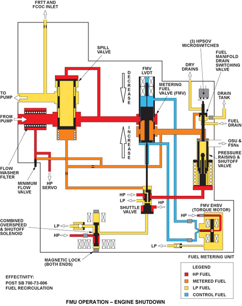
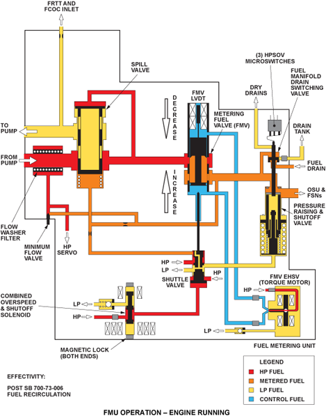
Fuel Metering Unit (FMU)
The FMU is on the fuel pump unit and meters the fuel required by the engine in response to the Electronic Engine Controller (EEC). The FMU also provides servo pressure that is used as the motive forces for the Variable Stator Vane (VSV) Actuator. The manufacturer sets a minimum fuel flow in the FMU, and this is always a higher flow than is necessary.
In the event of an engine overspeed, the FMU shuts off fuel to the fuel spray nozzles. The FMU also drains the fuel manifold into the drains tank on engine shutdown. The FMU is mounted on the Fuel Pump Unit via four bolts.
Fuel enters the FMU through a port in the mounting face; unused fuel (spill return) is returned to the inlet of the fuel pump unit through a similar port in the mounting face. The flow of fuel through the spill valve is in proportion to the constant pressure differential across the fuel metering valve. All other electrical and fuel inlet/outlet connections are external.
Fuel is bled off before the minimum flow valve as servo pressure and goes through internal holes in the unit. This HP servo pressure opens or closes valves in the FMU as a function of the unit.
The FMU converts EEC signals to servo pressure signals by the use of Electro-Hydraulic Servo Valves (EHSVs). There are two integral EHSVs; one for fuel metering control and one for control of the VSV actuator.
A different function of the FMU is to shut off the fuel supply to the engine when necessary. This comes as an instruction from the flight compartment, or automatically as a signal from the EEC. The fuel shutoff system is controlled by the Combined Overspeed and Shutoff Solenoid (COSS) which directs HP or LP servo pressure to the HP Shutoff Valve (HPSOV) via a shuttle valve. The COSS supplies fuel pressure to move a shuttle valve. The fuel metering-valve plunger can also move the shuttle valve. The position of the shuttle valve causes the high pressure shut-off valve (HPSOV) to open or close. Three HPSOV switches provide feedback of HPSOV position back to the EEC. A valve ensures that fuel in the manifold is returned to the drains tank upon engine shutdown.
When you make a selection in the flight compartment to stop the engine, the OFF side of the COSS energizes. This lets the HP servo pressure move the shuttle valve to the closed position. The shuttle valve piston removes the fuel which goes back through the LP servo line. In this position, the shuttle valve lets HP servo pressure through to push on the HPSOV to close it. The EEC also senses the selection in the flight compartment and sends a signal to the FMU.
The spill valve senses FMV upstream pressure at its head which is balanced by a combination of a spring and FMV downstream pressure. The position of the FMV is controlled by its EHSV/Electro-Hydraulic Servo Valve, and its position is fed back to the EEC by the FMVs LVDT (i.e. position sensor).
The shuttle valve controls the pressure to the HPSOV as directed by the COSS. The COSS (Combined Overspeed and Shutoff Solenoid) consists of:
- A RUN solenoid hardwired to the ENG RUN switch for the Fuel On function when the switch is ON
- An OFF solenoid hardwired to the opposite side of the switch to perform the Fuel Off function when the switch is OFF
- Two additional OFF solenoids, which are for control by the EEC Independent Overspeed Protection (IOP) system
During normal operating conditions, the ON solenoid is energized by an ON signal from the ENG RUN switch, which enables the supply of metered fuel flow to start the engine and/or maintain the engine running. The COSS logic dictates that in case of an engine overspeed, a single command to turn the fuel off from the IOP must override the fuel ON signal above.

Engine Shutdown
When the engine is stopped, the last movement of the HPSOV pushes a plunger to open a drains switching valve. This lets fuel drain from the manifolds back through the valve in the FMU to the drains tank. The HPSOV also operates position-indicator micro-switches, two for the EEC and one for the airframe. The EEC switches are set to close when the HPSOV is open, and to open when the HPSOV is closed.
The engine is shut down by the FMU in one of three ways:
- Fuel switch to OFF: This causes the COSS OFF solenoid to energize, allowing HP fuel pressure onto the shuttle valve head, moving it to the shutdown position, the displaced fluid from the piston head being returned to the LP fuel system. In this position, the shuttle valve allows HP fuel servo pressure to act on the head of the HPSOV that is now forced closed
- EHSV to close the FMV. This causes the FMV push rod to move the shuttle valve into the shutdown position and the HPSOV closes as above
- IOP demand: this will move the COSS to the shutdown position irrespective of demand for fuel initiated by cockpit controls
Engine Running
During the engine start procedure, the HPSOV must also open to let the fuel flow go through to the fuel nozzles. In the engine stopped condition, the FMV is in the closed position. The plunger thus holds the shuttle valve in the closed position and the HPSOV stays closed. When you make a selection to start the engine, the COSS energizes. This lets HP servo pressure push the shuttle valve away from the closed position and the plunger starts to open the FMV. The HPSOV stays closed until the metered flow is of sufficiently high pressure to open it against spring pressure.
A positive fuel flow will be obtained with the engine rotating provided that the ENG RUN switch is in the RUN position and that both IOP channels for that engine are not demanding engine shutdown. In this position the COSS allows HP servo pressure to act on the head of the shuttle valve, forcing it into the engine running position. This bleeds off the pressure on the HPSOV head to LP return pressure, allowing it to open when the HP metered flow is of sufficiently high pressure to overcome the spring force.
An EEC command to increase fuel flow will cause the EHSV to direct HP servo fuel to the FMV bottom piston, allowing it to open. This reduces the FMV pressure drop which is sensed by the spill valve.
The corresponding increase in fuel flow through the FMV increases the pressure drop until the desired flow rate has been achieved. At this point, the pressure drop across the FMV has regained its former value. The sequence of events for deceleration is the opposite.
At low engine speeds there are large quantities of unwanted fuel sent back to the inlet side of the HP pump. The pump must not use this fuel again because the fuel temperature becomes too high. To prevent this, there is a spill diverter valve which lets unwanted fuel flow to the inlet side of the fuel-cooled oil cooler (FCOC). During this condition, the HP servo pressure is low and LP servo pressure, plus a spring, holds the valve open. At high engine speeds the HP servo pressure is higher than the LP servo pressure plus the spring and the diverter valve closes.
Dedicated Generator
The dedicated generator is an electro-magnetic device which changes mechanical energy to electrical energy and supplies electrical power to the EEC. It has a stator housing which is on the front face of the accessory gearbox, on the right side. The accessory gearbox turns a permanent magnet rotor, which turns in the stator housing and causes electrical power. The stator housing has four sets of windings, two for each channel of the EEC. Electrical power goes to the EEC through harnesses which connect to receptacles on the end face of the stator housing.
The generator produces four outputs; two three-phase power and two single-phase power. The three-phase power is supplied to the central processor unit (CPU) of the EEC and the FADEC system external loads and the single-phase power is supplied to the EEC IOPs. Thus the two channels of the EEC are energized independently. The dedicated generator will supply full system electrical power when the HP compressor speed (N2) is more than 35%. When N2 speed is less than 35%, or if the dedicated generator becomes defective, the power comes from the aircraft system.

EEC ARINC 429 Digital Data Bus Interface
The EEC receives ARINC 429 digital data directly from the three Air Data Computers (ADC), and the three Integrated Avionics Computers (IAC).
The ADC inputs to the EEC are Pressure Altitude (P0), Total Pressure (P20), Total Air Temperature (T20), Calibrated Airspeed (CAS), and Mach Number (MN). The interface provides the capability to detect, isolate, and accommodate failures of these signals.
The IAC performs the major interface between the aircraft systems and the FADEC system. The EEC inputs are used to control engine systems - i.e. TR operation, engine synchronization, BMC demands (P30), etc. The EEC outputs engine data to the IAC - i.e. all CAIMS data, TLA, trend data, etc.


P20/T20 Probe
The EEC measures the inlet total pressure (P20), and temperature (T20), which come independently from the P20/T20 probe. The P20/T20 probe attaches on the inner skin of the intake barrel at the top dead center (TDC) with nuts and bolts. Access to the probe is through a panel in the top surface of the nose cowl. The routing of two electrical harnesses and the P20 tube is through the rear bulkhead of the nose cowl. From this bulkhead, the P20 tube goes to the P20 connector on the EEC. The electrical harnesses connect to other related electrical harnesses, one to the EEC and the other to the engine/airframe interface.
The probe points forward in the air intake and collects air through two small inlets. The pressure inlet supplies the air through one tube to the P20 connector on the EEC. Adjacent to the other inlet there are two thermocouple elements which sense the temperature of the air. Some of this air flows out through holes in the rear of the probe, but the air that the thermocouple elements sense does not move. A change in the air temperature causes a change in the resistance value of the thermocouple elements. This changes the output value which the EEC calculates.
The probe has an electrical heater element which is energized to prevent the collection of ice. Electrical power comes from the 115 VAC aircraft electrical-power supply to heat the probe.

P50 Rakes and Manifolds
P50 is the core engine exhaust pressure. The air is bled from the rear of the LP turbine where it flows into four outlet guide vanes (OGVs). The OGVs which are at equal distances around the exhaust case, each have four small diameter tube inlets in the leading edge. These let the P50 air collect in the OGVs which are hollow. External tubes connect the outlets from the four OGVs together as a manifold, which connects to an air tube.
The routing of the air tube is through the services fairing tray and up the right side of the bypass duct. It connects to the pressure transducer module on the EEC. There is a water trap in the P50 tube to make sure water does not collect in the transducer. The P50 air is measured by a vibrating cylinder pressure transducer and compared to P20 inlet pressure. The EEC compares the ratio between P50 and P20 and calculates the engine pressure ratio (EPR).


T30 Thermocouples
There are two T30 thermocouples installed through the combustion case, one at each side on the engine horizontal center-line. They each have a triangular flange which attaches to the case with bolts. A metal C-type seal prevents air leakage and a decrease of engine pressure. The thermocouples have two elements, one made of nickel-aluminum and the other of nickel-chromium. The elements are in a short probe which is open to air temperature. Each thermocouple connects to a different channel of the EEC.
The thermocouples continuously monitor the temperature of the air (T30) as it goes from the HP compressor. A sudden decrease in the T30 temperature is an indication of bad weather (the EEC senses this). In this condition, the compressed air has a high moisture content which can cause the engine to extinguish. If there is a decrease in T30 temperature, the EEC will make applicable control adjustments.
- The bleed valves are open to help the removal of water and prevent compressor surge
- The engine speed automatically increases by a sufficient quantity as a result of the open bleed valves
- An automatic selection of continuous ignition occurs to make sure the engine is not extinguished

System Interface
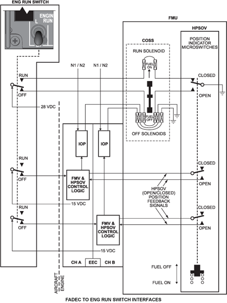
FADEC to ENGINE RUN Switch Interface
The ENG RUN switch can be manually selected by the pilot to either the OFF or RUN positions to inhibit or allow the EEC to control the engine. The ENG RUN switch interfaces with both the EEC and the HPSOV to ensure the following capabilities:
- To manually control the opening and closure of the HPSOV using two solenoid coils in the FMU
- To provide indications to the EEC of the ENG RUN switch position and to perform a dual channel IOP shutdown following a transition from RUN to OFF
ENG RUN Switch to FMU COSS Interface
The ENG RUN switch turns on 28 VDC airframe power to the COSS to open/close the HPSOV. Each of the open/close coils is activated through micro switches monitoring the HPSOV position. With the HPSOV closed, only the opening coil can be energized, and with the HPSOV open, only the closure coil can be energized.
Note:
The OFF signal from the ENG RUN switch to the FMV and the HPSOV logic will also redatum the IOP’s overspeed trip point values to cause an overspeed shutdown, as well as a normal shutdown.
When engine RPM falls below idle, the normal IOP trip point values are restored; the purpose of this is to exercise the IOP circuitry so as to verify its correct functioning.
Any faults which prevent an IOP-initiated shutdown will initiate an amber EICAS message of L/R FADEC FAIL.