


05/30/16
Overview
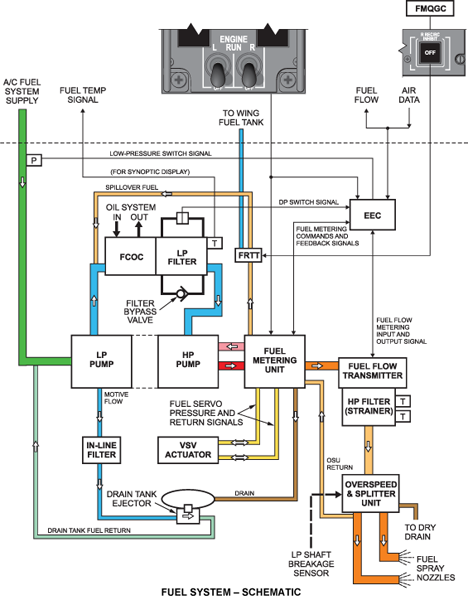
The fuel distribution system gives fuel to the core engine for combustion, and supplies it to give servo pressure for specified engine units.
The fuel goes into the engine fuel system at the aircraft/engine interface. The low pressure (LP) fuel pump sends the fuel through the LP fuel filter, to the high pressure (HP) fuel pump. The HP fuel pump sends the fuel through the fuel metering unit (FMU) and the HP fuel filter, to the fuel-manifold splitter unit (MSU). At the MSU, the fuel is sent to the upper and lower fuel manifolds and to the 20 fuel nozzles. Fuel pressure is also necessary for the operation of specified engine units. The FMU supplies a specified quantity of fuel to give servo pressure for the function that follows:
- Operation of the variable stator vane (VSV) compressor-airflow control-system
05/30/16
Fuel Pump
The fuel pump unit produces a supply pressure for the LP fuel system, including the motive flow for a Drains Tank Ejector/DTE. The unit also supplies HP fuel to the FMU (Fuel Metering Unit) at a sufficiently high pressure and flow rate to satisfy metered fuel flow requirements to the spray nozzles and the VSV actuator. The fuel pump unit is mounted at the center rear pad of the AGB by a V-band clamp.
The fuel pump unit contains both the LP and HP pumps. The LP pump is a centrifugal pump. The HP pump is a gear type pump and has an integral pressure relief valve. Both pumps are driven by the accessory gearbox via a single shaft.
The pump unit has mounting provisions and transfer ports for the Fuel Metering Unit / FMU. In addition, it has ports for supply and return lines to the Fuel Cooled Oil Cooler/FCOC, the LP filter, and the LP pump inlet, all of which are fitted with three-bolt flanges. The two ports for the drains tank are both fitted with standard union fittings.
The LP fuel pump gets fuel from the aircraft fuel tanks. Fuel supplied to the fuel pump unit inlet port is pressurized by the centrifugal boost stage and delivered via one of the ports to the FCOC/LP fuel filter and then to the HP fuel pump. In normal operation, the fuel supply to the FCOC/LP fuel filter is approximately 150 psi. Return flow from the FCOC/LP filter enters the pump through another port, passes through a size no. 4 mesh strainer and enters into the gear stage. The fuel is further pressurized by the pumping gears and is discharged to the FMU.
A direct acting pressure relief valve is fitted in the HP pump discharge, to protect the HP fuel system against over pressurization. The relief valve opens at 1,400 ± 25 psid and returns fuel flow to the inlet side of the HP pump. Unused return fuel from the FMU enters the pump through a second interconnecting passage on the FMU mounting pad. The return fuel is ducted internally back to the HP pump inlet.


05/30/16
LP Fuel Filter
The LP filter is the fuel systems primary filter and it removes debris from the fuel prior to the fuel entering the HP pump. The filter is mounted within the FCOC housing assembly.
The filter housing has a mounting feature for the combined fuel filter differential pressure switch and pop-out indicator. The filter element is a disposable 40 micron paper element.
It has a 10-micron filter (which cannot be cleaned) and is a line replaceable unit (LRU). If the fuel pressure across the filter increases to 25 psi (172.37 kPa), the fuel bypass valve opens to let the fuel flow continue to the HP fuel pump.
The filter is held in position by an end cap which features a spring-loaded mount for the element, an off-set drain hole, and a filter bypass pop-out type indicator. A bypass valve allows fuel to bypass the element in case of filter blockage.
Fuel enters the assembly through the fuel inlet where a tapping takes a signal to the filter P switch. Fuel is thereafter routed into the FCOC unit. On leaving the FCOC, the fuel passes through the central part of the filter, and exits via the outlet port. Here, two more tappings are taken, one to the differential pressure switch, and the other to a fuel temperature sensor.


05/30/16
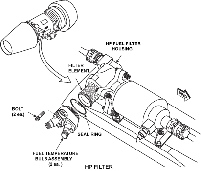
HP Fuel Filter
The HP filter prevents any foreign objects debris (FOD) downstream of the LP filter from being passed into the fuel manifold and causing possible blockage of the fuel spray nozzles. The HP filter has no bypass provisions and continued accumulation of FOD will result in complete blockage of fuel through the filter.
The HP fuel filter is located at the right center position of the engine, on the bypass duct. The filter assembly is bolted to the rear of the fuel flow transmitter and is connected to the fuel pipe via a standard pipe union. It takes HP fuel from the FMU. The HP filter assembly comprises a cleanable 250 micron stainless steel filter element inside an aluminum housing and is a LRU. It can be cleaned. The filter screws into a bolt-on end plate, which supplies a mounting feature for two temperature bulbs (discussed below under the heading fuel temperature bulbs).
Fuel enters the filter assembly and flows around and through the filter element. At the center of the element the fuel passes over the temperature transducers and then flows out of the fuel outlet union.
Fuel Temperature Bulbs
Two temperature bulbs/probes are mounted in the HP fuel filter assembly, on the right side of the bypass duct, each having a single rubber O-ring seal. These bulbs were previously used in an air cooled oil cooler (ACOC) system that has now become obsolete. These probes do not form part of any circuitry. However, they are delivered with these engines, and the EEC monitors their validity.
Fuel Tubes and Fittings
Many of the fuel tubes are installed on their fuel system components by union nut connections. The fuel inlet tube to the HP fuel pump and the outlet tube from the FMU is a flange installed with bolts. The flanges have seal rings installed at the joint.

05/30/16
Fuel Manifold
The fuel manifold has three components, which together, go fully around the engine. The upper manifold has a left and a right part and each part supplies fuel to five fuel spray nozzles (FSNs). The upper right manifold supplies FSNs no. 1 to 5. The upper left manifold supplies FSNs no. 16 to 20. The lower manifold, which is one part, supplies FSNs no. 6 to 15. Each manifold is a two-part assembly. There is an inner manifold inside the outer manifold. This is to stop fuel leakage if the inner manifold becomes defective. The manifold is attached to brackets which are installed on the front flange of the combustion outer case. Each manifold outlet is connected to the related fuel spray nozzle with a different “pigtail” tube.
The fuel supply for the upper and lower manifolds is set independently. The lower manifold is supplied from one junction. The junction is at an equal distance from each end of the lower manifold. The upper manifold is supplied from one junction, but this divides immediately into two supplies. These connections are at the two ends of the upper manifold and give an equal supply of fuel to the upper nozzles.
Fuel from the OSU upper manifold outlet goes to a supply tube which is connected to the lower ends of both upper manifolds. Fuel from the OSU lower manifold outlet goes to the lower manifold inlet connection. This distribution arrangement minimizes any difference in fuel pressure between the FSNs at the top and bottom of the engine.

05/30/16
Fuel Spray Nozzles
The Fuel Spray Nozzles (FSNs) deliver the metered fuel into the combustion chamber for maximum efficiency combustion. Twenty (20) simplex FSNs are mounted on the combustion case, equally spaced around the engine. The upper or lower manifold supplies fuel to each nozzle. Each is bolted directly onto the casing by three bolts and a seal. The nozzle head locates into the combustion lining supplies fuel to the combustion area in the correct condition for ignition.
The fuel spray nozzles are numbered clockwise (as viewed from the rear), with No.1 nozzle at the 12 o'clock position. All FSNs are interchangeable. Fuel is routed from the fuel manifold to the fuel spray nozzles by individual distribution tubes.
Fuel passes along the nozzle body and to the head where it is forced through a narrow circumferential orifice. HP delivery air also passes through the nozzle and mixes with the fuel on exit. This combination of narrow fuel orifice and airflows causes the fuel to be forced into a fine spray, which is ideal for combustion.

05/30/16
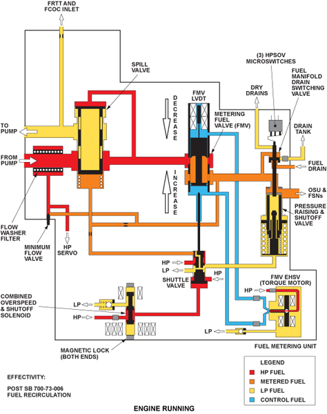
Overspeed and Splitter Unit
The overspeed and splitter unit splits the main fuel flow equally between the upper and lower fuel manifolds after ensuring that a minimum pressure exists upstream.
The OSU also has a fuel shutoff feature operated by the LP shaft failure sensing mechanism. The unit is bolted to the right side of the HP compressor casing via a bracket and three bolts.
The OSU contains two valves within an aluminum housing. The spring-loaded splitter valve distributes fuel to the two manifolds, and the overspeed valve provides fuel pressure to the back of the splitter valve, closing it in the event of LP shaft breakage detection. The overspeed valve has a latching spring.
The fuel-manifold splitter unit (MSU) is located adjacent to the bleed-valve solenoid control on the lower right side of the core engine. HP fuel is supplied to the MSU. The MSU has two functions. Its primary function is to supply the upper and lower manifolds with equal quantities of fuel for combustion. Fuel pressure forces the splittervalve open to supply each manifold. Its other function is to stop thefuel supply to the fuel nozzles immediately if the LP turbine-shaft becomes defective.
This is done mechanically by the operation of the emergency shut-off cable. One end of the cable is connected to the overspeed valve in the MSU. The other end of the cable is located in the LP turbine housing. If the LP turbine shaft becomes defective, the cable moves a piston in the MSU. This lets a secondary fuel supply and the spring pressure close the overspeed valve, and thus stops the fuel supply.
At engine shutdown, unwanted fuel from the upper and lower manifolds drains through the MSU to the FMU and back to the drain tank.
The splitter valve is held closed by action of the spring until the upstream pressure increases to overcome the spring pressure (60 psi), at which point the valve opens and allows fuel to pass into the manifolds. The metering ports are nominally identical and produce negligible difference in head between the upper and lower manifold.
In the event of LP shaft breakage detection, the overspeed valve will open and latch, inlet fuel pressure will act on the rod side of the splitter valve. The spring and fuel pressure overcomes the inlet fuel pressure on the piston head and the valve closes.
When the splitter valve is in the closed position, a groove around the piston allows the upper manifold to drain into the lower manifold, which is subsequently drained into the drain tank via a valve in the FMU.


09/20/18
Fuel Return to Tank System
The purpose of the fuel return to tank (FRTT) system is to maintain the fuel tank temperature above a minimum value during high altitude, long-range flights. The FRTT takes hot fuel from the excess capacity of the engine HP pump and recirculates it back to the aircraft wing tanks.
This excess fuel is a portion of the spill flow, which is circulating around the HP pump because the HP pump always delivers fuel in excess of engine requirements. This is because the pump is sized for the windmill relight case, where light-up fuel flow has to be accomplished at very low rotational speeds. This results in a significant pump over capacity at higher engine speeds.
The fuel flow rate through the fixed orifice is highest when the engine is at idle, and lowest when the engine is at full power. At all flow rates sufficient heat energy is available in the fuel for the fuel recirculation system to maintain the fuel temperature in the wing tanks above the fuel freezing point.
The majority of the spill flow is returned back into the HP pump inlet. A portion of this spill flow is redirected to the FRTT, as described above. With the FRTT system OFF, the excess fuel that passes from the fuel metering unit to the FRTT valve is then sent to the inlet of the fuel cooled oil cooler. With the FRTT system ON, the fuel is directed back to the aircraft wing tanks and the path to the fuel cooled oil cooler is closed.
Refer to chapter 28-26-00 for more information on the FRTT check valve and shutoff valve.
Note:
Information on the FRTT shutoff valve is also available in chapter 73 of the Rolls-Royce Engine Manuals.
Fuel Drain Tank
The drain tank collects fuel from the fuel manifold after engine shutdown and delivers it back to the LP pump inlet during the next engine run. The tank is bolted to the bypass duct rear flange and to the exhaust case support flange via two brackets, and is located at the 6 o’clock position.
The tank capacity is sufficient for two engine shutdowns, following aborted start attempts. The tank has an integral ejector, the drain tank ejector (DTE) which uses LP pump delivery fuel as a motive force to empty the tank. The DTE has a float valve to prevent ingestion of air into the DTE return. A dry drain is fitted to the top of the tank to dump fuel overboard in the event of DTE malfunction.
A (removable and washable) strainer in the DTE inlet prevents blockage of the ejector. A check valve in the ejector prevents ejector flow from entering the tank.
LP fuel flow passes through the inlet strainer and then through a converging duct. This lowers the pressure sufficiently to draw any fuel from the tank into the return line, which passes the fuel to the inlet of the LP fuel pump.
Fuel from the LP pump outlet is unfiltered. Any fuel debris could eventually block the DTE filter, causing the tank to overfill on subsequent engine shutdown.

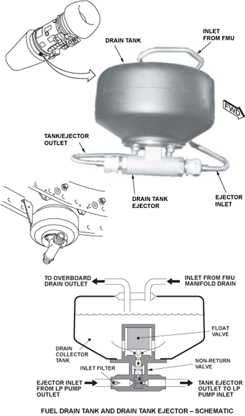
DTE In-Line Filter
Fitted to the rear of the structural bypass cowl at the 7 o’clock position is a DTE in-line filter that prevents blockage of DTE pump conical filter.
The filter element is a 200-micron aluminum alloy mesh. The element can be hand-cleaned as described in the Aircraft Maintenance Manual. A filter bowl that secures the element is screwed on to the filter housing and is further secured by a spring clip. The whole assembly is mounted on the structural bypass case by three bolts.
The filter is situated downstream of the LP fuel pump and upstream of the drain tank ejector. Fuel from the LP fuel pump outlet passes through the filter element and then on to the drain tank ejector pump. This ensures that the fuel is clean prior to entering the ejector and does not contaminate it.
System Operation
Fuel is supplied to the LP pump at a pressure of 20 psi (137.90 kPa) and goes from the pump at 150 psi (1,034.22 kPa). This keeps sufficient pressure in the adjacent system for changes in the fuel pressure and temperature across the FCOC and the LP fuel filter. A supply of pressurized fuel is also sent through the fuel drain-tank ejector valve to make a suction in the drain tank. This takes fuel from the drain tank back to the supply side of the LP pump.
The LP fuel goes through the FCOC to the LP fuel filter. If the pressure difference across the filter increases to 25 psi (172.37 kPa), the LP fuel-filter bypass-valve will open. This supplies fuel flow to the HP fuel pump if the filter becomes clogged. The fuel is supplied to the HP fuel pump at a pressure of 150 psi (1,034.22 kPa).
The HP fuel pump supplies pressurized fuel to the FMU. In correct operation, the fuel supply pressure at the FMU is 1,200 psi (8,273.76 kPa). When an indication is given to stop engine operation, the fuel metering valve (FMV) in the FMU closes. This stops the fuel flow to the fuel nozzles, but the fuel continues to move while the accessory drives turn. The unwanted fuel from the HP pump goes back to the supply side of the HP pump.
While the fuel is not required, or the accessory drives continue to turn, the fuel will continue to go back to the supply side of the HP pump. If there is too much fuel pressure at the pump exit, up to 1,400 psi (9,652.72 kPa), the HP relief valve will open. The unwanted HP fuel will go back to the supply side of the HP pump.
The HP fuel is supplied through the FMU and then goes through the HP fuel filter. The HP filter gives the last protection for the fuel nozzles. HP fuel is then supplied to the MSU. During engine start, the splitter valve in the MSU stays closed under spring pressure until the fuel pressure is more than 60 psi (413.69 kPa). At this pressure, the valve opens to let fuel go to the upper and lower fuel manifolds.
If the LP shaft becomes defective, the MSU overspeed valve is mechanically moved by the emergency shut-off cable. This movement of the overspeed valve lets a secondary fuel supply go behind the splitter valve. This secondary fuel supply increases the pressure behind the valve and closes it. This stops the fuel flow to the fuel nozzles. The valve cannot be set again until the unit is removed from the engine. When engine operation is stopped, openings in the MSU let unwanted fuel from the manifolds drain to the drain tank.
The HP fuel goes to the upper and lower manifolds that supply the 20 fuel nozzles with fuel for the combustion system. The fuel is given to the combustion area as a spray for satisfactory ignition.

09/16/20
Component Location Index
| Component Location Index | |||
|---|---|---|---|
| IDENT | DESCRIPTION | LOCATION | EMM REF |
| - | FUEL PUMP | ZONE(S) 430/440 | 73-11-01 |
| - | LP FUEL FILTER | ZONE(S) 430/440 | 73-12-01 |
| - | HP FUEL FILTER | ZONE(S) 430/440 | 73-12-02 |
| - | FUEL MANIFOLD | ZONE(S) 430/440 | 73-12-03 |
| - | FUEL TUBES AND FITTINGS | ZONE(S) 430/440 | 73-12-04 |
| - | FUEL NOZZLES | ZONE(S) 430/440 | 73-13-01 |
| - | FUEL MANIFOLD SPLITTER UNIT | ZONE(S) 430/440 | 73-13-02 |