


05/31/16
Overview
The function of the fuel indicating system is to give an indication of the condition of the fuel system to the crew and for engine control.
The indicating system supplies fuel flow, fuel temperature and fuel pressure data to the EEC. The EEC transmits indications of fuel flow, fuel temperature and low fuel pressure to the flight-compartment engine indication and crew alerting system (EICAS) display. Indications of LP fuel filter blockage are also transmitted if this condition occurs.
The fuel temperature transducers give information that is used to get satisfactory engine operation. The information that the EEC receives from the fuel flow transmitter and the LP fuel filter differential-pressure switch are for monitor functions only. The fuel low-pressure switch is connected directly to the EICAS.

05/31/16
Fuel Flow Transmitter
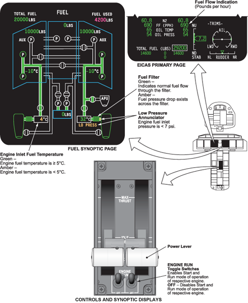
The fuel flow transmitter is located on the RH side of the bypass duct above the engine centerline, and serves to initiate a digital indication of the respective engine fuel flow on the EICAS primary page (just below the N2 rpm displays). It is located between the HP shut-off valve (HPSOV) in the fuel metering unit (FMU) and the HP fuel filter. It has a cylindrical shape and attaches to the bypass duct and to the HP fuel filter. Two bolts and a locating dowel attach the transmitter to a forward bracket on the bypass duct, while four bolts, including the two above, fasten the HP fuel filter assembly to the rear of the transmitter.
The FFT is in a straight piece of fuel tube. This makes sure that the flow becomes constant and linear before it touches the FFT. This gives an accurate indication. The FFT gives "START" and "STOP" inputs to channel B of the EEC. The EEC gives a flow value in the correct condition for an indication to the EICAS.
The mechanism inside the transmitter housing converts mass flow rate to an angular displacement between two magnets, which rotate with the transmitter mechanism. A pair of electrical coils sense the time difference between the passing of the two magnets. This time difference is used to establish a direct relationship between the angular displacement of the magnets and the fuel flow rate. The fuel flow transmitter and the HP fuel filter are two separate LRUs.


Fuel Temperature Transducers
The engine has two fuel temperature transducers. Their function is to sense HP fuel temperature. The transducers are located on the right side of the bypass duct at the top center position of the engine. The transducers are located in the same unit as the HP fuel filter. Each transducer has a sealing ring and is installed with two bolts.
The system transducers are two nickel bulb thermometers. Each transducer is connected to a channel of the EEC. Two transducers are used to make sure that the temperature indication is accurate. The transducer system uses a current source that is constant to operate the resistance of the transducers. This makes a voltage that has to change with the resistance to keep a constant current. This gives a value to the EEC.

Fuel Low-Pressure Switch
There is one fuel low-pressure switch on the engine. The fuel low-pressure switch is located in the fuel supply from the aircraft fuel tank to the engine. It is installed on a bracket in the bypass duct, adjacent to the fuel-cooled oil cooler. It gives an indication at the EICAS display if the fuel supply from the aircraft fuel tank to the LP fuel pump decreases below 7 psig (48.26 kPa). The EICAS message is inhibited when the engine is not operating.
An amber LO PRESS icon under each LP fuel filter temperature indication will illuminate anytime fuel pressure in the main fuel supply line is below 7 psig.

05/31/16
DP Switch and Indicator Unit
There is one LP fuel-filter differential-pressure switch on the engine. It is located in the LP fuel filter bypass-flow. The switch gives an indication of a LP fuel filter blockage before there is a total blockage. The switch monitors the fuel pressure at the LP fuel filter supply and exit positions. The DP switch is bolted to the rear face of the LP fuel filter housing on the FCOC assembly and provides an advance flight deck alert of an impending LP fuel filter bypass. It is set to trigger at 5 psid and initiates the applicable EICAS message/s reading FUEL FILTER.
The DP indicator is mounted at the center of the filter retaining cap and is a magnetic pressure piston and locking-ball type of "pop-out" mechanism. It is set to pop-out at a differential pressure of 21.5 psid. The LP filter bypass valve is set to open at 25 psid.
The pop-out indicator button can not be reset unless the filter retaining cap is removed and inverted. This is intended to ensure that the filter will be inspected at the same time.
If the difference in the pressures becomes out of limits, a value is sent to channel B of the EEC. This value is then sent to the flight compartment for indication and maintenance functions. A secondary value is also sent from channel B to channel A in the EEC.


System Indications
Engine fuel flow digital readouts are displayed on the EICAS primary page. Temperature of fuel (in °C) at the outlet side of the LP filter is displayed in digits on the fuel synoptic (status) page.
An impending bypass of the LP filter, or the failure of the filter bypass DP switch, on a single engine is notified to the crew by a CAS advisory message (in cyan) reading L FUEL FILTER or R FUEL FILTER. When one of the above two faults occurs at the same time on both engines, a cautionary (amber) CAS message reading L FUEL FILTER, R FUEL FILTER is displayed. If either or both filter(s) should have an impending bypass condition, the respective LP fuel filter symbol(s) will change color from green to amber on the fuel synoptic (status) page.
The throttle levers and the ENGINE RUN switches. Which are the main controls of the engines.

09/16/20
Component Location Index
| Component Location Index | |||
|---|---|---|---|
| IDENT | DESCRIPTION | LOCATION | EMM REF |
| - | FUEL FLOW TRANSMITTER | ZONE(S) 430/440 | 73-31-01 |
| - | FUEL TEMPERATURE TRANSDUCER | ZONE(S) 430/440 | 73-32-01 |
| - | FUEL LOW-PRESSURE SWITCH | ZONE(S) 430/440 | 73-33-01 |
| - | LP FUEL-FILTER DIFFERENTIAL PRESSURE-SWITCH | ZONE(S) 430/440 | 73-34-01 |