


06/01/16
Overview
The compressor airflow control system consists of variable angle stator vanes and the bleed valves, also called handling bleed valves. The function of the compressor control system is to make sure that the compressor operates smoothly during its full speed range.
The variable inlet guide vanes and the first three stator vane stages of the HP compressor are collectively called the variable stator vanes (VSVs). They are coupled together and their position is controlled by a single fuel pressure-driven actuator in response to EEC commands. The VSVs control the angle at which the air enters the first four stages of the HP compressor and thereby ensure a smooth airflow at lower engine speeds.
The compressor airflow control system also consists of four pneumatically operated bleed valves (also known as handling bleed valves). The handling bleed valves offload air from the 5th and 8th stages of the HP compressor into the bypass duct. Actuation of the bleed valves is provided by the bleed valve solenoid unit which is controlled by the EEC. To keep the engine operation satisfactory, the EEC continuously monitors the engine performance and adjusts the airflow through the compressor.
There are two main characteristics built into the HP compressor. These are high efficiency and operational stability, both occurring at high engine speeds. However, at low engine speeds, the compressor airflow is less stable, and tends to cause compressor surges, which lead to potentially dangerous engine stalls.
- Variable angle stator vanes are employed to redirect the airflow into the HP compressor at the best aerodynamic angle for each set of specific operating conditions prevailing in the engine
- Air bleed valves, also called Handling Bleed Valves, are located at strategic points on the HP compressor. They increase the axial velocity of the air entering the compressor by lowering the pressure rise across its forward stages
Both the features above are used during steady state and transient engine operations. Air flow control during acceleration allows optimum additional fuel to be metered into the engine, permitting increased thrust and stall-free acceleration rates.
In addition, both these methods are used to aid in recovery from any compressor surges and to enhance the optimum performance of the engine, (producing the maximum thrust at any given rpm and fuel flow).
06/01/16
Variable Stator Vanes (VSV) and 4 Unison Rings
Each set of variable stator vanes is connected by a circumferential unison ring to provide synchronous movement. The unison rings are installed around the outside of the compressor case.
Each unison ring is of square section and is in two semicircular halves, connected by bridge pieces. Levers are installed in bushings at equal distance around each ring. The levers are connected to the vane spindles by a bolt.
The vane spindles are in bushings in the compressor case. When the ring turns, the levers move together to change the angle of the vanes. This gives a satisfactory angle at which the airflow goes in the first four stages of the compressor.
A drive bracket on each unison ring is connected to the VSV actuator via a configuration of bellcrank levers and rods.
Linear movement of the actuator rotates the unison rings in synchronization to change the angle of attack of the variable vanes/stators according to EEC requiremen
Variable Stator Vane Control System
The variable inlet guide vanes (VIGVs) and the first three stator vane stages of the HP compressor are collectively called the variable stator vanes (VSVs). They are coupled together and their position is controlled by a single fuel pressure-driven actuator in response to EEC commands.
The VSV coupling also controls the buffer air valve (BAV), which admits HP4 sealing air to the front bearing chamber and to the gearbox/accessory seals at low engine speeds. The VSVs control the angle at which the air enters the first four stages of the HP compressor and thereby ensure a smooth airflow at lower engine speeds. This is known as the off-design conditions (the design condition being cruise power and higher). The system is moved between the minimum and maximum permissible angles (relative to the engine center line) by the engine electronic control (EEC), via an electrohydraulic servovalve (EHSV).
The EHSV is mounted in the fuel metering unit (FMU), and provides servo pressure to the VSV actuator. An LVDT provides position feedback to the EEC and forms part of the actuator assembly. VSV scheduling is a function of compressor airflow. It is calculated by the EEC using N2 speed, T20 and T26, the latter being computed by the EEC from T20 and N1 (corrected N2 speed).


06/01/16
VSV Actuator
The VSV actuator controls the position of the HP compressor VIGVs and VSVs. It is also used to operate the Buffer Air Valve (BAV). The actuator is at the bottom left side of the compressor case, near the front. The VSV actuator is mounted on the HP compressor casing by four bolts, at about the 7 o’ clock position of the engine.
The VSV actuator comprises a differential area piston housed in an aluminum body. The piston is connected to a series of bellcrank levers to turn the synchronous unison rings. When the ram moves, the fuel which goes from the actuator back to the control valve, goes through the other opening. The linkage system which connects the VSV rings to the actuator includes a link which operates a buffer air valve. This valve attaches to, and operates with, the VSV actuator. Thus, when the VSV actuator moves, the buffer air valve moves. The buffer air valve controls the supply of HP stage 4 sealing air to the front bearing chamber. EEC feedback is via a Linear Voltage Differential Transducer (LVDT) with two windings.
These are a part of the piston ram and electrically connect to the EEC. The LVDT is an electromechanical transducer that gives an electrical signal which is in proportion to the position of the ram. There are two electrical connectors on the actuator, one for each channel of the EEC.
During removal/installation, the actuator is rig-pinned at a nominal cruise (or retracted) position before removing/fitting the locating dowel. The LVDT to actuator piston relationships is rig-set at the factory and does not need any adjustment during removal/replacement of the actuator.
The VSV actuator is operated by high-pressure fuel supplied by an Electro Hydraulic Servo Valve (EHSV) which directs flow to one of two sides of the piston to change the angle of the VSVs as necessary. The actuator exerts a larger force when it extends than when it retracts.
When the ram extends, the vanes will move to the closed (low speed) position. When the ram retracts the vanes will move to the open position. The position of the ram is continuously transmitted to the EEC by two LVDTs, which are a part of the piston ram.
Electro-Hydraulic Servo Valve (EHSV)
The EHSV controls the VSV actuator servo pressure; it is located within the fuel metering unit (FMU) and forms an integral part of it. The EHSV is operated by an integral torque motor which is electrically connected to the EEC.
The torque motor has a separate winding for each EEC channel. Only one channel will be in control at any time. The torque motor controls the shuttle valve which, in turn, allows HP servo pressure to be fed to the actuator directly.
When a change in VSV angle is necessary, the EEC changes the position of the torque motor. Movement of the torque motor results in the displacement of the shuttle valve. Openings in the shuttle valve control the rate of flow, direction and pressure to each side of the actuator piston (ram). The HP servo pressure is directed to one side of the valve, the other side being open to LP return.
When the VSV angle is satisfactory, the EEC returns the torque motor and the spool valve to the null (neutral) position. Further movement of the VSV actuator is therefore prevented, i.e., the actuator is hydraulically locked.
The EHSV is biased to ensure that the actuator piston is driven towards the low speed stop for a zero torque motor current. This is considered to be the fail-safe position for the system.
Note:
If a malfunction of the EHSV is indicated by CAIMS, the FMU has to be changed, since it is an integral part of the FMU.


Variable Stator Vane Scheduling
The schedule specifies the required steady state VSV schedule by commanding the VSV bell crank angle actuator position as a function of N2 and T26. This function is known as N2 corrected speed. If a transient, surge or reverse condition is detected by the EEC, the vane resets will be applied. These will set the bell crank angle position as a function of altitude, at a rate defined by the EEC.
Transient detection is to detect an engine acceleration or deceleration by anticipation of EPR command change, change in idle condition, P30 being detected below a threshold value, surge detection or heat soakage detection and to indicate sustained acceleration or deceleration from the rate of change of N2. Further, reverse operation is detected by the EEC as a transient condition.

06/01/16
HP Compressor Handling Bleed System
The system consists of four pneumatically operated bleed valves (also known as Handling Bleed Valves) which offload air from the 5th and 8th stages of the HP compressor into the bypass duct.
Actuation of the bleed valves is provided by the bleed valve solenoid control block which contains four solenoid operated servo valves.
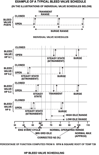
The solenoid is controlled by the EEC which schedules the bleed valve operations in both steady state and transient conditions as a computed function of N2 RPM and the square root of temperature T26 (T26 being synthesized from T20 and N1 RPM). [This function is known by the mathematical symbol (N2RT26)].
The valves use HP10 air as servo operating force and may be commanded to be in either of two positions-fully open or fully closed. Applying power to the solenoid coil closes the servo area of the solenoid control valves allowing the bleed valve to close.
There is no feedback of any valve position to the EEC. Electrical fault detection is carried out by voltage and current monitoring between the EEC and the solenoid valves.
The EEC is able to open bleed valves to ensure stable airflow during inclement weather conditions (as indicated by T30). In addition, bleed valves are opened to reestablish stable conditions following an engine surge (recognized as a sudden drop in P30).
Bleed Valve Solenoid Unit
The solenoid control block is on the bottom right side of the HP compressor case, adjacent to the fuel-manifold splitter unit. The solenoid block has four solenoid housings, a vent valve body and a valve body assembly held together with bolts. Each solenoid housing contains two windings, each dedicated to a separate EEC channel.
The solenoid block contains four electrically operated valves which allow independent control of HP10 servo air to the handling bleed valves, as directed by the EEC. The solenoid unit is positioned at the 4 o’ clock position of the engine, and bolted directly onto the HP compressor casing by means of four bolts.
The unit is connected to the compressor casing by four bolts, two of which are through slotted lugs which facilitate removal and installation. There is one HP stage 10 air inlet connection and four outlet connections to the bleed valves. All the air and electrical connections are at the rear of the unit.
The four solenoid valves, which operate independently, control the flow of air to their related bleed valves. Each solenoid housing has two windings on a solenoid core. The windings each connect to a channel of the EEC. The solenoid wires are held in two twelve pin receptacles which have different keyways to prevent incorrect connection. When a solenoid is energized, a solenoid valve pulls to the solenoid core against a spring.
Two twelve-pin receptacles receive signals from the EEC, one from channel A when active, or channel B. Different keyway configurations in each receptacle prevents incorrect connection.


Handling Bleed Valves
The handling bleed valves allow air to be bled from the HP compressor. This ensures engine stability at low engine speeds, allows surge free engine acceleration and deceleration and enables engine recovery from compressor surge.
The bleed valves are installed two on each side of the engine, one above and one below the center line. The HP8 bleed valve is installed at the top left position and the HP5 bleed valves are installed at the other positions.
At each bleed valve position there is a stand pipe assembly which is attached to the compressor case. A mounting flange on the stand pipe has two location dowels, and nine holes with thin wall inserts. An air tube supplies HP10 air to a connector in the stand pipe. A hole through the flange aligns this with the bleed valve body.
Each bleed valve has a body assembly and a piston housing which are contained in a noise attenuator. This configuration is attached to the flange of the stand pipe with bolts. The body assembly includes a valve seat and a carbon bearing in which the valve is installed.
At the end of the valve stem there is a piston which is installed in the piston housing with a body spring. A hole in the piston housing aligns with the hole in the valve body. Thus HP10 air can flow through the stand pipe, body assembly and piston housing to the inside of the piston.


Handling Bleed Valve Schedule
Engine not Running, Static Condition
In this condition the solenoid vent valve and inlet valve are held on their seats by spring force. The bleed valves are forced into the open position by the valve spring.
Engine Running, Solenoid De-energized
When the solenoids are de-energized, each solenoid vent valve is held on its seat by spring force, which opens the servo vent to release air from the top surface of the plunger piston to atmosphere. HP10 compressor air acts on the underside of the plunger piston to hold it in position. The inlet valve is held closed by spring force and HP10 air pressure. In this configuration the bleed valve upper chamber and HP10 bleed valve supply tube are allowed to vent. The bleed valves are held open by spring force and HP5 or HP8 compressor air acting against the underside of the valve assembly.
Engine Running, Solenoid Energized
In this condition the following happens:
- The solenoid vent valve is pulled towards the solenoid core, opening the servo vent valve. This vents air from the top of the plunger piston and HP10 air closes the inlet valve. Air is now vented from the bleed valve chamber and the bleed valve closes
- The handling bleed valves are held closed by HP compressor stage 5 or 8 air at takeoff, climb and cruise phases of flight. Failure of a solenoid (de-energized) will cause the respective bleed valve to open
- Loss of HP10 servo air pressure would not have an effect on the position of a bleed valve which is closed, however, this valve would not open when commanded by the EEC

System Operation
Engine Start to Idle
Before engine start, all bleed valves are open. VSVs will be on their low speed stop, having been positioned there during the previous engine shutdown. If the VSVs have been opened for maintenance reasons, they will return to the low speed stop during initial rotation of the engine.
| Point A | The VSVs are commanded by the EEC to move off the low speed stop. No change to bleed valves. |
|---|---|
| Point B | Bleed valves HP5.2, HP8, and HP5.3 close (almost at the same time, but in that order), HP5.1 remains open. |
| Point C | Engine at idle. At this point three bleed valves are closed and the VSVs are at a controlled minimum angle. |
Acceleration from Idle to Full Power
| Point C | As the engine is commanded to accelerate, bleed valve HP5.3 is opened. |
|---|---|
| Point D | The VSV’s angular displacement rate-of-change increases. |
| Point E | Bleed valve HP5.1 closes. |
| Point F | Bleed valve HP5.3 closes. All bleed valves are now closed. |
| Point G | VSVs reach high speed stop, or fully open. The engine continues to accelerate up to steady state rated power. |
Deceleration will be the reverse of the above. The bleed valve operating points will be slightly different because of the built-in hysteresis.

09/17/20
Component Location Index
| Component Location Index | |||
|---|---|---|---|
| IDENT | DESCRIPTION | LOCATION | EMM REF |
| - | VARIABLE STATOR-VANE ACTUATOR | ZONE(S) 430/440 | 75-31-01 |
| - | BLEED VALVE SOLENOID-CONTROL-BLOCK | ZONE(S) 430/440 | 75-31-02 |
| - | BLEED VALVES | ZONE(S) 430/440 | 75-31-03 |