


Overview
The function of the cooling system is to keep the engine at a satisfactory temperature internally and below the cowling.
Ram air, bypass air and internal core air are the sources used to keep different parts of the engine cool. External air keeps the two fire zones cool. Internally, air bleeds from different stages of the HP compressor to keep very hot parts cool during engine operation.
Accessories and Zones
The function of the accessories and zones cooling system is to keep the risk of fire to a minimum. This is done with an airflow which removes flammable fumes and keeps a satisfactory temperature below the cowls.
The power plant has two fire-resistant zones which are isolated from each other by fireproof bulkheads and fairings. Both zones contain flammable fluid systems and a flow of air is necessary to remove flammable gas. The airflow through each zone also keeps the system components at a satisfactory temperature. A fire detection and extinguishing system monitors each zone for fire and sends a fire extinguishing agent through tubes and nozzles if there is a fire.
Zone 1
Zone 1 is the annular space below the cowls which extends axially from the air inlet cowl to the thrust reverser. The front of the zone is the air-inlet cowl rear-bulkhead and the rear is the thrust-reverser front-frame. These two components are fire resistant over the full 360 degrees. The inner surface of the zone includes the ring which holds the inlet cowl, the LP compressor case and the bypass duct. This zone contains most of the engine accessories and includes the fuel, oil and hydraulic tubes and the accessory gearbox. At the top of the zone there is an isolated compartment which gives protection to the engine electronic controller (EEC).
The aircraft forward speed causes ram air to flow through the zone from the top to the bottom. External air goes into the zone through two flush inlets in the upper cowl on the center line. One of these inlets is in front of and one is behind the EEC compartment. A short tube with a Y-piece, attached to the inside of each inlet, supplies the air equally around the zone. The used air goes overboard through an outlet in the lower cowl at the bottom of the zone.
Zone 2
Zone 2 has two areas which are isolated. An annular space around the core engine, between the fairings and the engine casings, has a firewall at each end. The front firewall is the rear face of the torsion box intercase and the rear firewall is at the turbine casing. The other part of the zone is the area in the bypass services fairing at the bottom of the engine. The bypass services fairing touches the core engine fairing and the area is isolated from zone 1 by the interservices sealing plate. The core engine fairings, bypass services fairing, sealing plate and related seals are all fireproof.
The zone 2 annular space contains the variable stator vane (VSV) mechanism and actuator, and the bleed valve solenoid-control-block. There are also fuel and oil tubes and the routing of most of these is at the bottom of the zone. The bypass services fairing also contains flammable fluid tubes, and the stage 5 and stage 8 air ducts. Bypass air goes into the annular space through three small inlets at the front of the zone. Two of these inlets are in the bottom quadrant and the other one at the top on the center line.
Through the bottom inlets the airflow decreases the temperature of the VSV actuator and the bleed valve solenoid-control-block. The airflow through the top inlet removes air pockets where fumes could collect if there was a fluid leak. This air flows down through the zone towards the rear. The bypass services fairing also has a small air inlet at the front near the bottom. This airflow makes sure that flammable gas does not collect at the front of the services area.
The rear of the zone uses air from the turbine casing cooling system. This air comes through from two sources which are opposite each other on the horizontal center line. The air flows down through the zone to the exit which is at the rear of the bypass services fairing. Used cooling air from the two sources mix together and go out of this exit into the bypass flow.

06/01/16
Engine Cooling and Sealing
The function of the engine cooling and sealing system is to keep the engine at a satisfactory temperature during operation. It also seals the bearing chambers and the accessory gearbox.
Air bleeds from different stages of the HP compressor to keep the internal engine temperature satisfactory. Some of this air goes through external tubes to the bearing chambers and the accessory gearbox. A buffer air valve, which is open at low engine power, controls one source of air. Parts of the engine which are at different pressures are isolated from each other by labyrinth seals. Air supplied to the outer surface of some of these seals prevents or controls the internal leakage of oil.
The air bleeds from the HP Compressor stages that follow:
- Stage 2 (Fan Air)
- Stage 4 (Buffer Air)
- Stage 6
- Stage 10

Fan Air
Fan air flows through the turbine outlet guide vanes (OGVs), first to cool the OGVs and then the rear face of the LP turbine stage 2 disc and thereafter, the air baffle and the stirrup assembly of the emergency fuel shutoff system. The fan air next flows into the engine exhaust gas stream between the LP turbine stage 2 blade roots and the turbine outlet guide vanes.
Buffer Air
Air under pressure which helps in isolating or keeping apart from one another, those areas of the engine which are at different pressures, is called Buffer air. Buffer air is supplied to both the Front Bearing Chamber (FBC) and AGB seals.
The FBC and AGB seals are fed by either Stage 2 air (at high engine power settings) or by Stage 4 air (at lower power settings). The change over between Stage 2 and Stage 4 air is achieved through a Buffer Air Valve (BAV) which operates in conjunction with the variable stator vane (VSV) actuator mechanism.
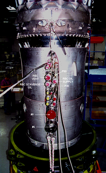
The RBC HP4 air exhaust is monitored for oil fire by means of a detector.
| Engine at Idle Power | Engine at Max Takeoff Power | |||||
|---|---|---|---|---|---|---|
| Bleed Stage | Nominal Air Flow in lb/sec | Nominal Press. in psi | Nominal temp. in °C | Nominal Air Flow in lb/sec | Nominal Press. in psi | Nominal temp. in °C |
| 5 | 1.6 | 19 | 77 | 8.4 | 100 | 277 |
| 8 | 2.2 | 30 | 132 | 12 | 210 | 407 |


Stage 4 Air
Stage 2 air seals the front bearing chamber (FBC). At low engine power, stage 4 air together with stage 2 air seal the FBC. Stage 4 air bleeds from the compressor casing directly into a buffer air valve. The valve, which operates with the variable stator vane (VSV) mechanism, controls this supply to the FBC. The valve is open when the engine starts and stays open until the engine speed increases to a set limit. External tubes bring the stage 4 air to the outer side of the labyrinth oil seals, to prevent oil leakage. When the buffer air valve closes, stage 2 air will keep the front bearing chamber sealed.
Stage 4 air, controlled by the buffer air valve, also goes through an external tube to the accessory gearbox (AGB). The component location faces of the AGB must be sealed to prevent oil leakage and oil system contamination. The air goes through holes in the gearbox to labyrinth seals at each of the faces. The air isolates the different accessory faces and goes out through the related component dry drain. When the buffer air valve closes, a continuous supply of stage 2 air seals the gearbox faces.
Stage 4 air also bleeds from the compressor case at four different locations to seal the rear bearing chamber. This air comes continuously through external tubes which go through the bearing chamber support struts. The air goes to the outer side of the labyrinth seals to prevent oil leakage. Some of the air mixes with the oil to cause an air/oil mist in the bearing chamber. There is also a controlled leakage of some stage 4 air through labyrinth seals to mix with stage 6 air. Used stage 4 air goes overboard through the breather.
Stage 2 Air
Air bleeds from the compressor case at the variable stator vane, second stage (VSV2) position. It is continuously supplied to the FBC through a tube. The same source of stage 2 air also goes to the AGB through a different tube. The air tubes which go to the FBC and the AGB connect to the stage 4 tube from the buffer air valve. The function of the stage 2 air is the same as that of the stage 4 air which goes to the FBC and the AGB.
Buffer Air Valve
The Buffer Air Valve is installed on the left side of the compressor case adjacent to the VSV actuator. A link connects the valve to the VSV mechanism so that the valve operates with the VSV actuator. The valve has a piston which attaches to a spindle and turns in a liner. There are slots in the piston which align with slots in the liner when the valve operates. The valve spindle has a weaker section which shears if the buffer air valve cannot turn. This lets the VSV mechanism stay free and prevents a malfunction of the system.
When the buffer air valve is open, stage 4 air goes to the FBC and the AGB. An air tube which attaches to the valve connects to pieces (that have the shape of a T) on the compressor case. Other tubes connect to the these pieces to supply the stage 4 air to the FBC and the AGB. The VSV actuator controls the operation of the buffer air valve directly.
When the actuator extends (VSVs closed), the slots in the piston align with slots in the liner and the valve opens. Stage 4 air can flow through the valve to help the stage 2 air to seal the FBC and the AGB. As the VSVs open, the mechanism turns the piston until the slots do not align and the buffer air valve closes. At this power setting, the stage 2 air supply is sufficient to seal the FBC and the AGB.
Stage 6
Air bleeds through exits in the annulus inner wall between the stage 6 rotor blades and stator vanes. It flows through the inside of the HP compressor drum, forward and aft, to keep the disks cool. At the front end, it flows through the HP compressor curvic coupling. The stage 6 air together with the stage 2/stage 4 air to seal the rear of the front bearing chamber.
At the rear of the HP compressor drum, the stage 6 air flows through the flange to the turbines. It keeps the rear face of the HP turbine stage 2 disk cool. Some stage 6 air flows aft along the LP turbine shaft into the front LP turbine space. The air also seals the edge of the LP turbine disks and bleeds from between the blade roots. This prevents a flow of exhaust gases in to the internal parts of the engine. The stage 6 air also pressurizes the intershaft seal of the rear bearing chamber.
Stage 10
HP stage 10 air is bled through exits in the inner wall of the annulus between the stage 10 rotor blades and the outlet guide vanes (OGV). This air is routed around the HP compressor shaft and cools the front face of the HP turbine stage 1 disc. Another source of HP10 air bleeds off after the compressor outlet diffuser and flows around the combustion liner. Some of this air then cools the nozzle guide vanes and joins the exhaust gas flow. The remainder flows through preswirl nozzles that control the level of the cooling airflow. The preswirl nozzles direct the air at the optimum angle to enter the HP1 turbine blade roots.
The HP10 air that enters the turbine blade roots goes in two directions, some of it flowing through the blades. After passing through the HP1 blades the air passes through the blade airfoil surface to provide film cooling. The remainder flows back out through the HP turbine stage 1 blade roots, between the HP turbine stage 1 and stage 2 discs. This cools the rear face of the stage 1 disc and the front face of the stage 2 disc. The air also cools the HP2 turbine blades, via holes on the blade root. Gas leakage at the shroudless blade tips is controlled by minimizing the tip clearances.
