


05/31/16
Overview
The hot air for engine anti-icing comes from the engine bleed system (stage 5 air). The function of the engine anti-icing system is not to let ice collect on the components that follow:
- Intake Cowl
- Fan Blades
- Spinner Point
- Aft of the Spinner
The hot air for engine anti-icing comes from the engine bleed system (stage 5 air) in the rear fuselage. This air goes through an insulated duct which connects to the cowl anti-icing valve. The duct has a venturi to keep the airflow to a limit if it, or the intake cowl duct breaks (while the cowl anti-icing valve is open). On the other side of the cowl anti-icing valve, the inner feed duct brings the hot air to a piccolo tube (inside the lip of the cowl leading edge). The hot air then collects in the outer exhaust duct (the inner feed duct goes through it) to release to the atmosphere through a vent assembly.
The ANTI-ICE control panel (a part of the bleed-air control panel) in the overhead control panel of the flight compartment has four three–position rotary switches. Two of these are for the engine intake cowls. These switches energize or remove the electrical power from the solenoid of the cowl anti-icing valve. This is to supply or to stop stage 5 air to the piccolo tube.
The P20/T20 probe, installed at the top dead center (TDC) of the engine inlet duct, has a 115 VAC heater that uses aircraft-supplied power.
The centrifugal force at the rear of the spinner releases collected ice. The inner diameter of the fan case has a glass-fiber ice-impact box at a position where the released ice hits. This breaks the ice into small pieces. Also, the spinner point is a soft rubber which twists during engine running to release the collected ice.

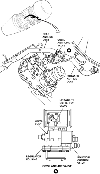
Cowl Anti-Icing Valve
The cowl anti-icing valve has a solenoid, a butterfly valve, and a pilot regulator valve. When there is no electrical power to the solenoid and no pressure in the duct, the butterfly valve stays open because of spring force. This lets the hot air go through to the piccolo tube in the leading edge of the intake cowl. If the downstream pressure increases, the pilot regulator valve (a needle valve) opens to cause higher pressure in the upper chamber. The butterfly valve starts to close and decreases the air flow to the intake cowl. When the solenoid is energized and the duct pressure is above 8 psi (55.2 kPa), the cowl anti-icing valve closes the butterfly valve (which stops the hot air to the piccolo tube).


Bleed-Air Control Panel
The ANTI-ICE control panel is the lower part of the bleed-air control panel. It has four three-position rotary switches, where two are L COWL and R COWL. The positions for each rotary switch are OFF, AUTO and ON. When the switch is set to OFF, the solenoid of the cowl anti-icing valve is continuously energized (and there is no stage 5 air supply for cowl anti-icing). When the switch is set to AUTO, the cowl anti-icing valve will open automatically when there is ice. When the switch is set to ON, the solenoid is de-energized and the cowl anti-icing valve opens if the air pressure is sufficient.

05/31/16
P20/T20 Probe
The P20/T20 probe is located at the 12 o’clock position in the engine inlet duct. The total pressure and total temperature at the engine inlet are sampled upstream and forward of the LP (N1) fan in the inlet duct.
The probe is a housing with a pipe connection, an electrical connection, and a bolt flange for mounting. The pipe is connected internally to an opening in the probe body, in line with the engine airflow.
Airflow through another opening is routed across a thermocouple junction, discharging back into the main engine flow. The probe contains a 115 VAC heater to provide anti-icing. P20 is used by the EEC for control related functions and in the calculation of EPR and Mach Number (Mn). T20 is similarly used for engine control functions and also in the determination of various EPR related functions such as calculation of command EPR.
The P20/T20 probe heater is on constantly if there is one of the conditions that follow :
- The engine operates and N2 is more than 35%
- The aircraft is in flight (weight-off-wheels)
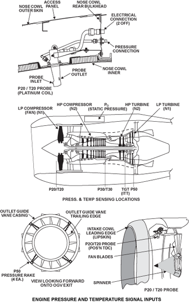

P50 Probes and Measurement
P50 is the total pressure at the core engine exhaust and is used by the EEC for EPR calculations. P50 air pressure is sensed by four pressure rakes, which are evenly placed around the turbine exit area and are integral parts of the turbine outlet guide vane (OGV) assembly. Each turbine OGV at these positions has four small diameter tubes, facing into the stage 2 LP turbine exhaust air. Exhaust air then enters into the hollow OGV.
External pipework around the turbine case connects the pressure sensed by this network to the EEC P50 pressure transducer in the pressure module, via the interservices fairing and the bypass duct.
The pressure transducer within the EEC pressure module provides a signal to both EEC channels and is temperature compensated.
P50 is validated as follows:
- Cross-check between EEC channels
- Prestart check to ensure P50 is the same as P0 (inhibited when an engine is windmilling sufficiently to cause a difference)
- Cross-checked against a synthesized value

09/17/20