


06/02/16
Overview
The engine power necessary is set in the flight compartment (throttle quadrant) and the engine electronic controller (EEC) controls it. Air temperature and pressure are sensed at different points on the engine and airframe, and these data go to the EEC. The EEC compares all the data it receives and calculates correct values. Electrical signals which relate to compressor shaft speed also go to the EEC. The EEC makes an analysis of these signals and calculates the correct engine speed.
The power indicating system gives continuous indications of the engine power and the compressor speeds on the primary page of the engine indicating and crew alerting system (EICAS). The power output is shown as engine pressure ratio (EPR) and the compressor speeds are shown as N1 (digital and analog) and N2 (digital) percent rpm.
06/02/16
Engine Pressure Ratio (EPR) Indicating
Similar to the practice in many other contemporary jet airplanes, the engine thrust on the Global aircraft is measured in a unit called the engine pressure ratio (EPR). It represents the pilot primary parameter for setting engine thrust. The EPR indicating system gives a flight compartment indication of the engine power adjustment.
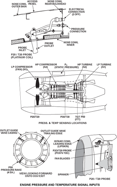
EPR is a numerical value of the engine power output. The two sources of pressure go to the engine electronic controller (EEC) which calibrates them and calculates a correct EPR value. A probe in the air intake measures the inlet air pressure (P20) and rakes behind the LP turbine measure the outlet pressure (P50).
The EPR value is the ratio of the pressure at the turbine exit area (P50) to the air inlet pressure (P20):
- EPR = Core Engine Exhaust Total Pressure (P50) divided by Engine Inlet Total Pressure (P20)
P20 is sensed by the EEC from a probe mounted in the engine intake. The P20 signal received from the intake probe is validated against aircraft P20 signal sensed by the three Air Data Computers (ADC) from aircraft mounted probes and transmitted to the EEC via the ARINC 429 digital data link.
The P20 probe pressure goes to a pressure transducer in the EEC. The EEC compares the P20 probe pressure with the ADC samples which are adjusted for altitude, air temperature and speed. The value of P20, adjusted for T20, is changed to a digital value and then used to calculate EPR.
P50 is sensed by a series of rakes in the engine exhaust; the combined pressure pick-up being fed to the EEC for P50 and EPR calculation. Raw EPR is calculated as a ratio of P50 and P20 and trims are applied at the EEC to generate a fully trimmed EPR for use in engine control and for engine displays.
An engine "pass-off trim" supplied by the Data Entry Plug (DEP), along with the EEC software, ensures that all engines display the same EPR for the same actual engine thrust level throughout the engine operating range.
The pressure transducer is a vibrating cylinder type which is in the EEC. The pressure transducer transmits the P50 pressure frequency to the two channels of the EEC which continuously measures the signals. An adjustment is made for temperature and the EEC calculates a corrected value of P50. This value is changed into a digital value and compared with the value of P20 to calculate EPR. A digital value of EPR goes to the engine indication and crew alerting system (EICAS) in the flight compartment.
P20/T20 Probes and Measurement
The P20/T20 probe, a single unit which points forward, is in the air intake at the top. A short pitot tube senses P20 pressure and a different air inlet measures T20. The P20/T20 probe is located at the 12 o’clock position in the engine inlet duct. The total pressure and total temperature at the engine inlet are sampled upstream and forward of the LP (N1) fan in the inlet duct.
The probe is a housing with a pipe connection, an electrical connection, and a bolt flange for mounting. The pipe is connected internally to an opening in the probe body, in line with the engine airflow.
Airflow through another opening is routed across a thermocouple junction, discharging back into the main engine flow. The probe contains a 115 VAC heater to provide anti-icing. The P20 pressure is transmitted through an air tube to a vibrating cylinder-type pressure-transmitter in the EEC. This measurement is calibrated for airspeed and mass flow. Two sensing elements in the probe change the T20 temperature into an electrical signal which goes to the EEC. P20 is used by the EEC for control related functions and in the calculation of EPR and Mach Number (Mn). T20 is similarly used for engine control functions and also in the determination of various EPR related functions such as calculation of command EPR.
P20 and T20 are validated using range-checks as follows:
| P20 | 1.0 to 23.0 psia |
|---|---|
| T20 | - 82 to 127 °C |
The P20 and T20 data obtained after validation is then corrected for installation effects.
P50 Probes and Measurement
P50 is the total pressure at the core engine exhaust and is used by the EEC for EPR calculations. P50 air pressure is sensed by four pressure rakes, which are evenly placed around the turbine exit area and are integral parts of the turbine outlet guide vane (OGV) assembly. Each turbine OGV at these positions has four small diameter tubes, facing into the stage 2 LP turbine exhaust air. Exhaust air then enters into the hollow OGV. All the rakes connect to a manifold. A tube supplies P50 pressure from the manifold to a pressure transducer. The P50 tube has a water trap.
External pipework around the turbine case connects the pressure sensed by this network to the EEC P50 pressure transducer in the pressure module, via the inter services fairing and the bypass duct. The pressure transducer within the EEC pressure module provides a signal to both EEC channels and is temperature compensated.
P50 is validated as follows:
- Cross-check between EEC channels
- Pre start check to ensure P50 is the same as P0 (inhibited when an engine is wind milling sufficiently to cause a difference)
- Cross-checked against a synthesized value

06/02/16
Speed Indicating System (N1 and N2)
The function of the shaft speed indicating system is to give a flight compartment indication of the speed of each compressor. A set of probes measure the speed of each compressor shaft independently. Magnetic speed probes, around the compressor shafts, transmit electrical signals to the EEC.
The speed at which each compressor shaft turns is measured independently and shaft speed indications show in the flight compartment. Speed probes transmit electrical signals to the engine electronic controller (EEC), which changes them into percentage equivalents. The low pressure (LP) compressor speed shows as N1 percent rpm on the engine indication and crew alerting system (EICAS) primary page. The high pressure (HP) compressor speed as N2 percent rpm on the EICAS primary page.
RPMs of the N1 and N2 spools are sensed directly from the engine. The N1 and N2 signals are used by the EEC for engine control functions and are displayed on EICAS as primary engine parameters. The same speed signals are also used by the Engine Vibration Monitor (EVM).
N1 is measured by four speed sensors per engine which are installed radially at positions around the LP compressor shaft. A phonic wheel is assembled to the shaft, adjacent to the probes, in the front bearing chamber. The phonic wheel has 43 teeth and one slot. As the shaft turns, the teeth cause a voltage in the probes which send electrical signals to the EEC. The frequency of this voltage is in proportion to the shaft speed. One of the sensors is connected to an Independent Overspeed Protection (IOP) channel A, and to EEC channel A. The second sensor is similarly connected to the other IOP channel B and to EEC channel B. The third is shared between the two EEC channels. The EEC validates the signals and passes them to the airframe via ARINC 429. The fourth N1 sensor gets a voltage from the slot in the phonic wheel and is hardwired to the airframe and is dedicated to EVM system and is used for engine vibration indication and for a one-shot LP system fan balancing. The signal is used to monitor the vibration levels of the LP compressor. None of the N1 probes is a line replaceable unit (LRU).
N2 is measured by four sensors which are installed in the front of the accessory gearbox, each being used in the same manner to the N1 sensors. The exception to this is the sensor that is hardwired to the EVM system is used solely for engine vibration indication. The probes make a magnetic circuit with the radial-drive bevel gear. The HP compressor shaft turns the accessory gearbox. As the HP compressor shaft turns, the bevel gear teeth cause a voltage in the speed probes. The frequency of this voltage is in proportion to the shaft speed. The probes send signals to the EEC where they are compared and a correct value goes to the flight compartment. The speed probe signals go the EEC (the two channels) and the IOP. The electrical connection of the probes to each IOP and EEC channel is the same as for the N1 probes. A fourth N2 speed probe, installed with the other three, connects directly to the aircraft. This is used to monitor the vibration levels of the HP compressor.
An intermediate connector on the engine allows easy changeover of speed probe destinations, so that they can be reconfigured if one fails. N1 and N2 speeds are indicated on EICAS as percentages and are primary engine parameters.

Speed Probes
All the speed probes are the same type, a single pole with a coil around it and a magnet at one end, contained in a case. The probe is installed so that there is a small clearance between the end of the probe and the teeth. As the N1 phonic wheel and the N2 bevel gear turn, the teeth make and break a magnetic flux path. This gives plus and minus charges (related to the shaft speed) which go to the EEC as electrical signals.
N1 Sensors
The N1 sensors are used for supplying the low pressure compressor speed as follows:
- Three sensors supply the EEC for:
- N1 EICAS indication
- N1 Redline limiting
- N1 Rating Control
- Thrust Control (Reverse Thrust)
- Independent Overspeed Protection
- One sensor supplies the EVM system for:
- Engine vibration indication
- ‘One shot’ LP fan balancing
The sensors are mounted in the front bearing housing around a phonic wheel that extends rearwards from the LP compressor shaft. The sensors consist of a magnetic pole and coil assembly encased within a composite (Kinel) body. The coil wires are terminated at two stainless steel pads on either side of the body and the output from the sensor is taken from these two pads.
The speed sensor is an electro magnetic sensor that produces an electromotive force when in close proximity to a rotating toothed ferrous (phonic) wheel. The sensor produces a positive and negative pulse for each tooth on the wheel. These pulses are then interrogated by the EEC to determine the N1 shaft speed.
The N1 sensors are not line replaceable, since access to the core engine is required for removal/replacement. However, it is possible to change the terminal connections between a faulty and a functional sensor on the front left-hand side of the EEC. Failure of N1 on both EEC channels will cause the engine to shut down. Both IOP lanes are required to be operational to allow aircraft dispatch.
N2 Probe
Three N2 probes are used by the EEC for the following:
- Variable Stator Vane Control
- Handling Bleed Valve Control
- Acceleration/Deceleration Control
- Start/Relight
- Redline Limiting
- Idle Control
- Surge Protection/Recovery
- Overspeed Protection
- N2 EICAS Indication
The fourth N2 probe is used by the EVM system for engine vibration indication. The N2 probes are mounted around the air starter drive casing on the front of the Accessory Gearbox.
Each N2 probe consists of a magnet, pole and coil assembly encased within a stainless steel body. The coil wires are terminated at an electrical receptacle, welded to the speed probe body. The signal is then taken from the designated pins in the receptacle.
The N2 speed probe is an electro-magnetic sensor that produces an electromotive force when in close proximity to a rotating toothed (bevel gear) ferrous wheel. The sensor produces a positive and a negative pulse for each tooth on the wheel. These pulses are then interrogated by the EEC to determine the N2 shaft speed.
If an N2 probe fails, it is possible to change the faulty probe. If the controlling channel loses its N2 signal, it can borrow the backup channels’ N2 signal, if it is valid. If the backup channel N2 signal is not valid, the controlling channel will use a synthesized value, and engine will reduce to idle N2 power.
