


Overview
The function of the temperature indicating system is to give a continuous indication of temperature in the area of the turbines.
During usual satisfactory engine operation, the temperature in the area of the turbines stays in specified limits. This is continuously monitored by dual-element thermocouples which transmit signals through a harness to the engine electronic controller (EEC). The EEC changes the signals into a temperature value which goes to the EICAS primary display in the flight compartment.
One other system uses an isolated thermocouple unit to sense cooling air temperature around the rear bearing chamber. If the temperature increases too much, a warning shows on the EICAS.
06/01/16
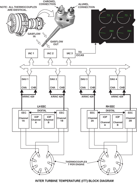
Inter-Turbine Temperature (ITT) Indicating
The function of the ITT indicating system is to give a continuous indication of turbine temperature on the engine indication and crew alerting system (EICAS) in the flight compartment.
The overall turbine temperature is critical to the health of an operating engine and forms the basis for the redline limit. A convenient place to measure the temperature that would be representative of the overall temperature of the turbine, is between the LP and the HP turbines. This temperature is called the Inter-turbine Temperature (ITT) and is used by the EEC during the entire engine start and operating range to control the engine and to relay it to the flight deck as a primary engine parameter.
Seven dual element thermocouples in the struts which hold the rear bearing chamber, mounted in LP nozzle guide vanes, are connected in parallel, and provide an average ITT (or Hot Junction Temperature) signal to each channel of the EEC via a single ITT harness per engine. The struts are at equal distance, and are included in the LP turbine nozzle guide vanes (NGVs). Around the outer surface of the turbine casing there are brackets. An ITT harness support ring attaches to these brackets. The electrical wires from the thermocouples go in one braided harness. Clips, installed around the circumference of the support ring, hold this harness in position. Each EEC channel has a sensor that measures the Cold Junction Temperature (CJT).
EEC processing of the signal involves converting the analog voltage received from the thermocouple harness to a digital value, taking into account the EEC reference temperature (CJT) and the value of ITT trim provided by the Data Entry Plug. The latter ensures that all engines for a particular rating and application have the same ITT redline.
The value of trimmed ITT is displayed in Degrees Celsius as a primary parameter on the EICAS primary display.
The ITT is validated as follows:
- A range check of the processed (trimmed) ITT
- A cross check with the other channel of the processed ITT
- If the cross check fails then the control channel will check its ITT circuitry to see if it has failed open. If it is open-circuited, the backup channel ITT signal is used


ITT Thermocouple
Seven thermocouple units are equally spaced around the LP turbine entry area positioned inside LP Nozzle Guide Vanes.
The probe consists of two junctions at different immersion (long and short reach), a mounting flange and a junction box that has threaded studs that interface with the thermocouple cable harness. The junctions are Type K Nickel-Aluminum/Nickel-Chromium (Alumel/Chromel).
The thermocouples send electrical signals to the engine electronic controller (EEC) which changes them into a temperature value. This value goes to the EICAS primary page, in the flight compartment. The EEC uses this ITT value as a primary engine limit during start and relight. The ITT must be satisfactory for continued engine operation.
Operation of the probe is based upon the principle that two dissimilar metals, when coupled in a complete circuit, will generate an electromotive force (EMF) proportional to the difference in temperature between a reference junction (at a known temperature) and a sensing junction (at a temperature to be measured).
The ITT probe is installed at an offset angle. Care must be taken to ensure that it is fully retracted before removal. The probe is not repairable.
06/01/16
Oil Fire Detection
The oil fire detection system monitors the internal cooling airflow of the LP turbine system. This system can sense a possible engine oil fire. The oil fire detection system continuously monitors the temperature of the LP turbine cooling airflow during all engine operations.
The RBC oil fire detection system monitors the temperature of the rear bearing chamber HP4 sealing air. The air is sampled from beneath the rear heat shield of the rear bearing chamber support structure, using a pair of thermocouples, which are housed in a single unit. The unit is located in an LP turbine nozzle guide vane (NGV) at the 4 o’clock position, with the engine viewed from the rear. At the outer position, the thermocouple assembly has a terminal block which attaches to the turbine case with two bolts. An electrical harness connects the terminal block to the two channels of the EEC. At the inner position, the thermocouple assembly is adjacent to the rear bearing chamber.
The thermocouple unit contains two K-type chromel/alumel thermocouple junctions mounted within a hollow tube that allows air to flow across the junctions. The thermocouples are independently wired to channels A and B of the EEC. The four studs on the thermocouple unit are color-coded green for alumel and white for chromel.
The thermocouple unit generates two independent electrical signals proportional to the sensed temperature, which are sent to channel A and channel B of the EEC. Temperature changes within the EEC are compensated for by sensors adjacent to the cold junction housed in the EEC CPU board.
The EEC is monitoring the cooling airflow of the LPT. The location of the thermocouple is such that any increase in temperature around the RBC will be detected indicating a possible fire in the RBC.
The logic within the EEC has the capability to recognize two levels of overheat. A higher trigger level is defined by the temperature limits of the LP turbine disc material and is subject to a 5 second confirmation time before the alerting status discrete is set. A lower level of overheat will be indicated following a 60-second confirmation time. This takes advantage of the thermal lag in the turbine discs to allow the critical phase of takeoff to be completed before posting the alert. When both channels of the EEC agree that there is an overheat condition, an amber caution message L/R ENGINE OVHT is displayed on EICAS.


06/01/16
Turbine Overheat Detection
The function of the turbine overheat-detection system is to monitor the internal cooling airflow for the high pressure (HP) turbine system. Two thermocouples which connect electrically to the engine electronic controller (EEC) measure the temperature adjacent to the rear bearing chamber. If the vortex reducer at the stage 6 cooling air offtake becomes defective, the cooling and sealing capacity decreases. Exhaust gas goes into the engine through the turbine blade roots and mix with the stage 6 air. This increases the internal temperature around the turbines. If the temperature increases to more than a safe limit, the EEC transmits a warning to the engine indicating and crew alerting system (EICAS) in the flight compartment.
The turbine overheat detection system monitors the turbine cooling airflow (HP6), using a pair of thermocouples. The air sampled is the HP6 cooling flow acting on the rear face of the HP stage 2 turbine disc.
The two thermocouples are housed in a single unit. The unit is located in the LP1 turbine nozzle guide vane (NGV) at the 1 o’clock position of the engine, viewed from the rear. At the outer position, the thermocouple assembly has a terminal block which attaches to the turbine case with two bolts. An electrical harness connects the terminal block to the two channels of the EEC. At the inner position, the thermocouple assembly is adjacent to the rear-bearing chamber support-strut.
The thermocouple unit contains two K-type chromel/alumel thermocouple junctions mounted within a hollow tube which allows air to flow across the junctions. The thermocouples are independently wired to channels A and B of the EEC. There are four terminals on the terminal block, one chromel and one alumel for each thermocouple. To easily identify them, the alumel terminals are larger and green, the chromel terminals smaller and white.
The thermocouple unit generates two independent electrical signals proportional to the sensed temperature, which are sent to the EEC. Temperature changes within the EEC are compensated for by sensors adjacent to the cold junction and on the application-specific integrated circuits (ASICs) board (two for each EEC channel, CPU and IOP/PSU boards).
The EEC overheat trigger requires a 60 second confirmation time prior to setting the indication. In addition, the indication is inhibited for 90 seconds following an acceleration. This prevents spurious indications of overheat, where there is no loss of engine integrity.
The thermocouples are together as one unit, and their function is to sense a condition of too much heat (possibly from an oil fire) in the rear bearing chamber. If the temperature detected reaches a preset limit, there exists a potential for damage to the HPT due to overheated (HPG) cooling air. When both channels of the EEC agree that there is an overheat condition, an amber caution message L/R ENGINE OVHT is displayed on EICAS.


09/18/20
Component Location Index
| Component Location Index | |||
|---|---|---|---|
| IDENT | DESCRIPTION | LOCATION | EMM REF |
| - | ITT THERMOCOUPLE | ZONE(S) 430/440 | 77-21-01 |
| - | OIL FIRE-DETECTION THERMOCOUPLE | ZONE(S) 400 | 77-22-01 |
| - | TURBINE OVERHEAT THERMOCOUPLE | ZONE(S) 430/440 | 77-23-01 |