


Overview
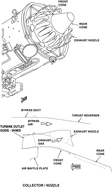
The function of the collector/nozzle is to mix the turbine exhaust with the bypass air. The cone assembly gives a smooth flow from the turbine and controls the mixer area.
The hot turbine gases and the bypass air become one air flow in the area between the exhaust unit and the exhaust cone. The turbine gases and the bypass air flow through lobes on the exhaust nozzle and mix. The result of this mixture of gases and air is a decrease of gas mixture velocity and a decrease in noise.
Exhaust Nozzle
The exhaust nozzle is a cylindrical shape with open ends. It has a flange around the forward edge and lobes around the circumference which decrease in depth to the forward edge. This flange attaches to the rear of the low pressure (LP) turbine exhaust case with bolts.
The exhaust mixer provides forced mixing of hot core gases and cold bypass air. This reduces the overall temperature of the engine exhaust to atmosphere increasing efficiency and reducing the noise signature of the engine.

06/02/16
Exhaust Cone
The front and rear cone forms a divergent duct (with the inner profile of the exhaust unit) and provides a smooth contour for the engine exhaust behind the turbine.
Front Cone
The front cone is a cylindrical structure with a flange at the forward and rear edges. The forward flange has bolt holes and the rear flange has captive nuts. The forward flange attaches to the rear of the LP turbine exhaust case with bolts.
Rear Cone
The rear cone has a round end and an internal flange around the front edge. Holes in the front flange align with the captive nuts on rear flange of the front cone. Access to the holes is through the outer surface of the cone. The rear cone attaches to the rear flange of the front cone with bolts.

09/22/20
Component Location Index
| Component Location Index | |||
|---|---|---|---|
| IDENT | DESCRIPTION | LOCATION | EMM REF |
| - | EXHAUST NOZZLE | ZONE(S) 430/440 | 78-10-01 |
| - | EXHAUST CONE | ZONE(S) 430/440 | 78-10-02 |