


06/01/16
Overview
The function of the thrust reverser system is supply reverse thrust when the aircraft has made a landing. This helps to decrease the speed of the aircraft during the landing.
The thrust reverser is of the pivoting door type. In normal flight the pivot doors are locked closed to provide a smooth nacelle and exhaust surface and allow all the exhaust gases to eject through the exhaust nozzle. A continuous rubber seal is fitted to the fixed structure to prevent gas leakage when the doors are closed.
When deployed, the upper and lower doors pivot to redirect almost all of the exhaust gases through the top and bottom of the nacelle. This eliminates forward thrust and provides a braking effect. Each door has a kicker plate attached to its front inner edge which is designed to ensure that the exhaust gases are ejected in the right direction. Door rotational travel is approximately 60 degrees.
The thrust reverser is operated by aircraft hydraulic pressure, and controlled both by the EEC and electrical signals from the aircraft. Selection is manual only and initiated from the flight deck throttle mounted thrust reverser select levers.
The thrust reverser controls consist of a left and right throttle lever, mounted in the throttle quadrant assembly. A thrust reverse select lever is incorporated in the throttle lever and is used to actuate the left or right thrust reverser system. Thrust reverser indication is provided on the primary EICAS display.
Each thrust reverser system (and exhaust unit) is properly oriented to suit the left or right installation and is not interchangeable between their two locations on the airplane. The differences between left and right are as follows:
- Door kicker plates are configured for left or right installation
- Exhaust nozzles are configured for left or right installation
- Directional control units are mounted on the top of the exhaust unit on the outboard side
- Linear variable transformers are mounted on outboard side of exhaust unit

Thrust Reverser
The function of the thrust reverser is to control the direction of flow of the engine exhaust gases. When the exhaust gases are pointed rearwards the power plant gives forward thrust for take-off and flight. When the exhaust gases are pointed forwards the power plant gives reverse thrust. This is used during landing to decrease the speed of the aircraft.
The thrust reverser is installed on the rear flange of the engine rear mount ring. The thrust reverser fixed structure has a front ring which is used as the attachment to the engine.
Behind the front ring is a torsion box which has two frames which contain the hydraulic and electrical circuits. The torsion box also contains the mount points for the door actuators, the direction control unit (DCU), the primary and tertiary locks and the door retracted switches. The surface of the torsion box has a layer of ceramic fabric which gives insulation from heat.
At the rear of the torsion box are the inner and outer side beams. These give the locations for the pivot pins of both the upper and lower pivoting doors. The outer side beam also has the mast for the breather system outlet.
The fixed structure has a seal installed around the edge of each of the openings for the pivoting doors. The seal prevents exhaust gas leaks from between the pivoting doors and the structure when the doors are closed. The seal is compressed as the doors move slightly in the close direction to unlock when reverse thrust is initially set.


Pivoting Doors
The thrust reverser has two pivoting doors, upper and lower, which are installed between the side beams and located by spherical bearings. When they are closed, the pivoting doors are flush with the fixed structure. This makes a duct which points the exhaust gases rearwards to give forward thrust. When they are open, the pivoting doors point the exhaust gases out and forwards through the fixed structure. This gives reverse thrust which helps to decrease the speed of the aircraft.
Each pivoting door is an assembly of carbon composite skins, with an aluminum honeycomb sandwich. The internal frames are a carbon fibre composite. A kicker plate is installed at the leading edge of the pivoting door. This helps point the exhaust gases in the correct direction when the pivoting doors are open. There are two access panels on the outer surface of each pivoting door to give access to the pivoting door actuator. The pivoting doors also have the strikers for the door stowed switches and the keepers for the tertiary locks.

06/01/16
Thrust Reverser Actuating System
The function of the actuating system is to move the pivoting doors of the thrust reverser into position to give forward or reverse thrust.
The actuating system moves and controls the pivoting doors of the thrust reverser. There are two positions for the pivoting doors, fully closed (forward thrust) and fully open (reverse thrust).
When the pivoting doors are in the closed position, the engine exhaust gases point rearwards through the exhaust nozzle. This gives forward thrust for take-off and flight. When the pivoting doors are in the open position, the doors point the exhaust gases outwards and forwards, through the nacelle structure. This gives reverse thrust, which helps to decrease the speed of the aircraft after touchdown.
The system is hydraulically operated and is electrically controlled by signals from the EEC and the aircraft.
Isolation Control Unit (ICU)
The isolation control unit (ICU) controls the supply of hydraulic system pressure to the thrust reverser system. The ICUs are located in the rear equipment bay, behind the fuselage rear pressure bulkhead.
The ICU contains the isolation valve which is controlled by a dual coil solenoid. Power supply is from the EEC, with each channel supplying its respective solenoid coil. The operating EEC channel supplies power to its respective solenoid coil during thrust reverser operation.
A 700 psig duplex pressure switch is located downstream in the ICU. It will monitor the pressurization of the thrust reverser system and provide an input to each EEC channel.
A manual inhibit lever is featured to prevent hydraulic operation of the thrust reverser during system maintenance and deactivation for MMEL dispatch. When the inhibit lever is rotated to inhibit, the isolation valve is physically held in the closed position. Inhibit status is indicated visually by red paint on the underside of the lever.
Warning:
The thrust reverser system must be inhibited before any maintenance or inspection is carried out on, in, or near the thrust reverser. Failure to do so could result in serious injury and/or damage. All safety procedures regarding the thrust reverser in the maintenance manual must be strictly followed.
When de-energized, the solenoid control valve isolates the thrust reverser actuation system from the aircraft hydraulic system pressure. In the de-energized state, the spring force and hydraulic pressure maintain the solenoid control valve double-ball shuttle valve seated in order to prevent the hydraulic pressure from passing through the isolation valve.
With no hydraulic pressure applied to the top of the isolation valve piston, its spring force keeps the piston in the closed position. This prevents hydraulic pressure from being routed downstream to the DCU.
When one solenoid coil is energized, the hydraulic pressure is allowed through to the top of the isolation valve piston. The isolation valve opens and allows pressure through to the pressure switch and to the DCU.
The ICU remains energized during the entire deploy/stow cycles and maintains hydraulic pressure to the Thrust Reverser. When the Thrust Reverser is stowed, the ICU is de-energized, removing hydraulic pressure from the Thrust Reverser.
To inhibit the ICU, the manual inhibit lever locking collar is pushed up and the manual inhibit lever is rotated 90 up to the lockout position. The locking collar is then released to lock the manual inhibit lever. This locks the isolation valve piston in the closed position, preventing hydraulic pressure from being routed to the DCU.


Direction Control Unit (DCU)
The directional control unit (DCU) controls hydraulic pressure to the head end side of the door actuators to provide the deploy force. It is mounted behind the exhaust unit forward bulkhead, on the outboard side, and can be accessed through a dedicated access panel.
The DCU contains the directional control valve which is controlled by a single coil solenoid valve. The unit also features a hydraulic system bleed port, which can be used to purge air from the system.
The directional control valve is spring-loaded to the stow position. The deploy solenoid control valve is spring-loaded and hydraulically loaded to the stow position when de-energized. The solenoid is controlled from the throttles stow/deploy microswitches and WOW signal from the LGECU or WSU (wheel spin-up)> 45 kt signal from the Brake Control Unit.
When the isolation valve opens in the ICU, hydraulic pressure passes directly through the DCU to both the upper and lower actuators rod ends to move the doors to the overstowed position. This is necessary for the release of the primary locks. The pressure also assists the directional control valve spring to keep it in the closed (stowed) position.
When the deploy solenoid valve is energized, it allows hydraulic pressure to sequentially release the two primary locks and then return to the DCU to move the directional control valve to the open (deployed) position.
When the directional control valve is in the deploy position, hydraulic pressure is directed to the actuators head end, deploying the thrust reverser doors. Displaced fluid from the actuator rod end transfers to the actuator head end through the directional control valve.
The hydraulic system can be bled of air from the DCU through the bleed port, with the deploy solenoid energized.
When forward thrust is set, the solenoid valve is de-energized. The direction control valve is in the closed position. This lets the hydraulic pressure from the ICU go to the retract side of the upper door actuator. The ICU directly supplies the retract side of the lower door actuator.
When the pivoting doors are fully closed, the solenoid valve is de-energized. The direction control valve is in the closed position. The DCU has no hydraulic pressure.

Door Actuator
The thrust reverser hydraulic actuators provide the mechanical force to open and close the thrust reverser doors. There are two door actuators, one for each pivoting door. They are mounted by bolts passing through spherical bearings at the forward and rear ends. This allows for self-alignment and slight angle changes during thrust reverser operation.
The actuator consists of a piston rod in an actuator body, which uses hydraulic pressure for operation. There are two hydraulic line connectors at the forward end. One is part of the actuator body and supplies hydraulic pressure to the head side of the piston for extension. The other connector is part of an externally mounted line which supplies hydraulic pressure through a flow snubber for hydraulic damping to the rod side of the piston for retraction. The gland/snubber assembly is installed internally to the open end of the cylinder. It is a seal to prevent hydraulic fluid leaks around the rod of the ram rod assembly. It is also a limiter for the piston when the actuator is fully extended.
Access to the front mount and hydraulic connectors is through the cowl doors. The rear mount is accessed through panels on the outside surface of the doors. The rear mount is adjustable to allow for actuator rigging to suit the installation.
Each thrust reverser utilizes its own side hydraulic system for independent operation. That is, the left side is powered by the No. 1 hydraulic system and the right by the No. 2 system. During deployment, hydraulic pressure is routed to the rod end from the DCU to overstow the thrust reverser doors so they can unlock. Then both sides of the piston are open to 3,000 psi hydraulic pressure. Due to the piston head side having a greater effective area, the piston will extend, causing the thrust reverser door to deploy.
During the stow cycle, the piston head side is opened to return hydraulic pressure. The higher hydraulic pressure on the rod end side will now have a greater force than the return pressure on the head side. Therefore, the piston will retract, causing the thrust reverser door to stow.


Primary Lock Actuator and Mechanism
The primary lock mechanism consists of a lock and actuator assembly. The primary lock holds the doors closed for normal flight. The mechanism is located level with the doors forward edge, on both sides of the exhaust unit at the horizontal centerline. Access is through a dedicated access panel.
Each assembly consists of a latching lever with hooks at both ends. These hooks engage with the upper and lower door hook plates. The latching lever is operated by a hydraulic actuator.
The primary lock actuators control the primary lock mechanism and are mounted just forward of the mechanism. Each actuator consists of an output rod (spring-loaded to lock) and a hydraulically operated release piston, incorporating a check valve.
When the DCU deploy solenoid is energized upon deploy selection, hydraulic pressure is directed to the first actuator. The release piston will compress the return spring to extend the output rod. After the piston has traveled a short distance, a port is opened to allow pressure to the second actuator, which is identical in operation.
When the second actuator has unlatched, hydraulic pressure is returned to the DCU to operate the direction control valve. The actuators will move the latching lever to the unlock position if the doors are in the overstowed position. The rubber door seals are designed to allow overstowing without causing seal damage.
During stow command, the DCU is de-energized and the thrust reverser stows. The primary lock latching levers will return to their normal position by spring force in the actuator.
During stowing, the mechanism is designed to latch automatically by actuator spring force. The door catches push the latch lever out of position during stowing. When the doors go to overstow, the latch lever and door catches reengage.


Tertiary Lock
The purpose of the tertiary lock is to prevent uncommanded thrust reverser deployment if the primary lock mechanism should fail. There are two tertiary locks, one per door, mounted at the 12 o’clock and 6 o’clock position, just forward of the thrust reverser doors. Access is through dedicated access panels.
The tertiary lock consists of a solenoid-operated spring-loaded plunger and a spring-loaded latch fork. A manual unlock feature is also provided. Microswitches indicate when the tertiary lock is unlocked to the flight deck.
The tertiary lock plunger (sear) will retract when the solenoid is energized by the WOW or wheel spin-up > 45 kt signal and the throttle stow/deploy microswitch. This will allow the lock fork to rotate to unlatch when the doors are opened under control of the hydraulic system. As the doors open, the latch fork is rotated to release the keeper bar. The latch fork is then held open by a large helicoil spring, ready to engage the keeper bar on door closing.
When stow is selected, the solenoid is de-energized, but the plunger is prevented from returning to the lock position by the latch fork until the door is closed. The solenoid is a dual coil unit where one coil is switched off by a microswitch contact in the open position. If the microswitch does not close, the unit can become too hot. To prevent overheating, a thermal fuse is installed in the circuit. A second microswitch contact is used as a position indicator.
The Tertiary lock incorporates a manual unlock feature. If the solenoid fails in the closed position, it prevents the lock plunger (sear) from retracting. With the sear in the extended position, the latch fork is unable to rotate to unlatch the reversers when deployed. A hexhead unlock mechanism is provided to manually retract the sear so that the reverser may be deployed.


Thrust-Reverser Hydraulic Tubes
The hydraulic tubes are installed in the torsion box and on the outer face of the torsion box. They transmit hydraulic pressure between the ICU, the DCU, the door actuators and the primary lock actuators. They also connect the thrust reverser hydraulic system with the aircraft hydraulic system.


Linear Variable Transducers (LVT)
The linear variable transducers (LVT) senses door position and provides a signal to the EEC. There are two dual LVT sensors, one per door, located between the door hinge points on the outboard side. Each dual LVT sensor provides a door position signal to each EEC channel.
Access is through a dedicated access panel for the head end. The rod end is accessible through the door hinge access panel. At the LVT head end there is a spherical ball mount which attaches to the exhaust unit structure. The threaded rod end screws into a turnbuckle type adjuster. The rigging adjuster provides LTV adjustments on installation.
The EEC provides an excitation current to the LVT. When the LVT rod moves in or out by the door pivot shaft lever, a voltage is generated proportionally to door position. This movement of the LVT rod is monitored continuously by both EEC channels, as a door deployed indication and as a percentage deployed value for each door.
The LVT monitors thrust reverser door position from the fully stowed position to the fully deployed position. This position shall be used for thrust limitation during door movement, in conjunction with the stow switch status, control of the throttle interlock solenoid, and control of the ICU isolation valve.
Inside the rod end side there is a bias spring which will retract the rod, should either end of the LVT become disconnected. The voltage ratio at this position is lower than the lower limit for overstow and is recognized as a probe disconnect to preclude engine deceleration to idle power.


Maintenance Test Enable Switch (MTES)
For maintenance purposes, the maintenance test enable switch (MTES) allows the thrust reverser to deploy and stow when the engine is not running. The only requirement will be hydraulic and electrical power and the cockpit throttle levers selection to command thrust reversers to deploy or stow.
The EEC normally will not energize the ICU isolation valve solenoid when the engine is not running. Even if the throttle lever is in the REVERSE IDLE position. Activation of the MTES overrides the EEC logic so the ICU isolation valve solenoid can be energized and allow hydraulic pressure to be directed to the thrust reverser system.
The MTES is a spring-loaded to the OFF position, guarded switch, which is mounted between the air turbine starter and the dedicated generator. To gain access, the lower fan cowl door must be opened.
To prevent the MTES from inadvertently energizing the ICU isolation valve solenoid, the EEC will only arm the MTES input under the following conditions:
- Engine not running
- Throttle lever moved from FORWARD to REVERSE thrust setting, or
- Throttle lever moved from REVERSE to FORWARD thrust setting
The MTES is only armed for 30 seconds following throttle lever movement. The timer is restarted during a subsequent throttle lever movement or when armed and the MTES is selected.


Control and Feedback System
The control and feedback system continuously monitors the position of the thrust-reverser pivoting doors. It supplies data about the door position to the EEC. The data is used by the EEC to control the thrust reverser and to supply indications to the flight compartment.
Stow Switches
There are two stow switches for each pivoting door, four switches total for each thrust reverser assembly. The microswitch type switches are installed on the rear face of the front structure torsion box. Access to the switches is available when the thrust reverser door is opened and through a dedicated access panel above each switch.
The stow switches are actuated whenever the door reaches the correctly stowed position. Each dual channel stow switch individually provides a signal to each EEC channel.
When the thrust reverser door is fully stowed, the door striker plate contacts the control lever of both stow switches. This provides closed circuit signals to both EEC channels. When the thrust reverser door moves away from the fully stowed position, the door striker is no longer in contact with the control lever of both stow switches. This provides open circuit signals to both EEC channels.
The stow switches shall be located in such a position as to be able to detect failure of a single primary lock assembly. This is while the door is engaged by the second primary lock and the tertiary lock during takeoff. The stow switch status shall be used for thrust limitation during stow, when the LVTs indicate stowed.
Door Position Sensor
There is one door position sensor for each pivoting door. The sensor has a fixed body that contains a movable rod and is installed at the outboard side of the thrust reverser.
The body of the sensor is attached to the side beam of the fixed structure. The end of the movable rod is attached to a lever on the outer pivot pin of the pivoting door. Thus, as the pivoting door moves the sensor is extended or retracted.
While the rod moves in the body, the output of the signal that the sensor sends to the EEC is changed. Thus, the sensor continuously monitors, and supplies an indication of, the pivoting door position.
The signal from the sensor is used to give a visual indication of thrust reverser position in the flight compartment. It is also used to prevent an increase of engine power to more than idle until the pivoting doors are a minimum of 60% open. This control is applied by the EEC.


06/01/16
System Operation
Thrust Reverser Controls
The thrust reverser controls consist of a left and a right engine throttle lever, mounted on the throttle quadrant assembly. Each throttle lever incorporates a reverse select (finger lift) lever, mounted on the forward face of the throttle lever. Raising the finger lift lever, when the throttle lever is in the FWD IDLE position, will allow the throttle lever to be retarded to the REV IDLE position. Further movement, rearward, of the throttle lever towards MAX REV will only occur when the thrust reverser is fully deployed. The thrust reverser settings range between the REV IDLE and the MAX REV positions, marked on the base plate of the quadrant assembly.


Deployment and Stowing
The throttle lever is first retarded to the FWD IDLE position. Next, the finger lift lever on the throttle is pulled up and held to initiate the selection of thrust reverser deployment. This action permits the throttle lever to be pulled back 6, up to, but not further aft of the REV IDLE position on the throttle quadrant.
A throttle interlock prevents any further throttle movement, thereby restricting engine acceleration, until the following signals are received by the EEC:
- Weight on Wheels (WOW) or Wheel Spin Up (WSU) >45 knots
- Throttle lever select relay signaling deploy command
- Doors open approximately 60% (40 degrees travel)
The throttle lever, which was so far physically restrained from being pulled further back beyond the REV IDLE position by the interlock, is now free to be pulled back all the way to the MAX REV position. The farther aft the throttle is pulled back towards this position, the higher will be the level of reverse thrust achieved.
Advancing the throttle lever to the REV IDLE stop will reengage the interlock and the engine will decelerate. When the engine is at idle and the EEC receives the doors closed signal from the door micro switches, the throttle can be advanced to the FWD IDLE position, and the finger lift levers will return to their normal position.
Deploy Cycle
When the reverse thrust request is initiated, by moving the throttle lever to the REV IDLE position (throttle RVDT -6 degrees movement and deploy switch), electrical signals are sent to operate the isolation control unit (ICU) and the directional control unit (DCU) solenoid valves and to release the tertiary locks. Movement of the ICU solenoid valve initiates three actions:
- A hydraulic pressure signal is generated by the ICU pressure switch
- Hydraulic pressure is routed to the DCU, and
- Hydraulic pressure is applied to the retract (rod end) side of both door actuators
When pressure is applied to the rod end of both actuators, it causes the thrust reverser to go into an overstow position, which is required to unlock the primary locks. Next, the DCU solenoid valve directs fluid to the primary lock actuators, thus allowing the locks to be released. Fluid, after sequentially unlocking the inboard and then the outboard primary locks, is allowed to return to the DCU control valve. As the control valve moves to the deploy position, the fluid is then directed to the head end of the door actuators, and the thrust reverser doors move to fully deployed position.
Once the doors are fully deployed, the ICU and DCU valves remain energized and maintain hydraulic pressure on the primary locks and TR actuators. The TR doors are hydraulically held open. The Tertiary locks torsion springs hold the forks in a position, ready for reengagement.
The following actions, generated by the various components of the system, such as door LVT, solenoid valves, and pressure switches, ensure the proper sequencing and operation of the thrust reverser when requested:
- EEC control energizes ICU solenoid control valve, which opens, allowing hydraulic pressure to the pressure switch and the DCU,
- A/C control tertiary locks unlock and DCU solenoid valve energized
- DCU routes hydraulic pressure to both door actuator rod ends to overstow
- DCU routes hydraulic pressure to inboard primary lock to unlock
- Inboard lock routes hydraulic pressure to outboard primary lock to unlock
- Outboard lock routes hydraulic pressure to move DCV to deploy
- DCU routes hyd pressure to both door actuator head ends to deploy
- EEC illuminates white REV indication LVT position feedback as unstowed
- LVT throttle interlock released when doors 60% deployed
- EEC white REV indication to green when both LVTs signal doors 90% deployed
Stow Cycle
To stow the Thrust Reverser, the throttle lever is simply moved to the forward IDLE position. The DCU solenoid valve is deenergized, and the hydraulic pressure is removed from the piston end of the door actuators. The pressure is directed to the rod end of the door actuators, moving the doors towards the Stowed position. The pressure at the Rod end moves the doors to the fully stowed position, venting the door actuator Head end to return. The Primary and Tertiary locks automatically reengage as the doors are retracted to the Stow position. Once the doors are stowed, the ICU solenoid valve is deenergized, and the system returns to the deenergized state.

Power Command Limitations
The pilot-commanded engine thrust level, as indicated to the EEC by the throttle resolvers, is limited in accordance with the position of the reverser.
In forward thrust, when the EEC senses door opening via the LVTs past the 10% position, engine power will be reduced to idle.
Similarly in reverse thrust, the engine will not begin to accelerate to the commanded level until the doors are open past 60% (approximately 40 degrees). The throttle interlock release occurs at the 60% door open position.

Thrust Reverser Control Circuit
Deploy LH No. 1 Thrust Reverser Function
The deploy LH no. 1 thrust reverser function is described as follows:
- The throttle lever is first retarded to the FWD IDLE position. The finger lift lever on the throttle is pulled up and held to allow the throttle lever to be retarded to the REV IDLE position. The throttle interlock prevents any further rearwards movement of the throttle lever
- At touchdown, the Landing Gear Electronic Control Unit (LGECU) and/or the Brake Control Unit (BCU) provide WOW/WSU inputs to SPDA 2 AND 4 as well as provide a ground for the T/R Deploy Relay. The TR deploy relay is located under the baggage compartment floor
- The EEC receives thrust reverser deploy command by the throttle RVDTs, moving to -6 degrees. Three stow/deploy switches in the throttle quadrant assembly (TQA) are also set to deploy. Two of these switches are used to provide DEPLOY CMD 1 and DEPLOY CMD 2 to SPDA 2 and 4 via DAU 1 and 2 and EMS CDU 1 and 2. The third switch is in the throttle interlock circuit which links either the tertiary lock switches or the EEC to the throttle interlock solenoid. Moving the throttle to reverse idle closes the two deploy command switches. When the third switch is set from stow to deploy, a ground from either tertiary lock is removed and the circuit to the EEC is completed in anticipation of the reverser doors reaching the 60% deployed position
- SPDA 2 provides 28 VDC to both Tertiary lock unlock circuits. The upper and lower Tertiary lock sears are withdrawn by the pull/hold coils and subsequently remain in the unlocked condition when unit switches deenergize the pull coils and keep the hold coils energized. A separate lock position switch within the unit provides an unlocked input to the DAUs
- SPDA 2 also energizes the DCU solenoid. The DCU spool valve remains spring loaded in the stow position until both primary locks are hydraulically unlocked
- With the aircraft on ground, the throttle in reverse idle and the engine running (or Maintenance Test Enable Switch selected), the controlling channel of the EEC will energize the hydraulic Isolation Control Unit (ICU) porting hydraulic system pressure to the DCU. A pressure switch on the ICU signals the EEC when hydraulic pressure is available to the DCU
- The DCU ports system hydraulic pressure directly to the rod end of the door actuators causing them to overstow. A separate hydraulic circuit via the energized DCU solenoid valve ports hydraulic pressure to unlock the outboard primary lock. The outboard primary lock then ports hydraulic pressure to unlock the inboard primary lock. Finally, the inboard primary lock ports hydraulic pressure back to the DCU causing the spool valve to move to the Deploy position. The hydraulic circuitry ensures that the reverser doors overstow before the primary locks are withdrawn
- The DCU now applies system hydraulic pressure to the head side of the door actuators in addition to the pressure already being applied to the rod side. The larger area on the actuator head side causes the actuators to extend and the reverser doors begin to deploy
- As the reverser doors deploy, four stow switches (two per door) signal the EEC that the doors are not stowed. Also, two LVDTs (one for each door) signal the actual door positions to the EEC. A normal reverser deployment will result in a white "REV" display within the N1 gauge on EICAS, indicating that the reverser is in transit. If the reverser fails to deploy, an amber caution L/R REVERSER FAIL message is posted on the CAS display
- As the doors reach 60%, the EEC provides a ground to the throttle interlock circuit and SPDA 4 energizes the throttle interlock solenoid. The throttle lever can now be moved to the full reverse thrust position. Also, the EEC signals EICAS and the White REV indication changes to Green
- When reverse is selected, the EEC uses N1 as the controlling parameter for setting engine thrust. With the throttle lever at the full reverse thrust position, the EEC keeps the engine at reverse idle until the reverser doors have reached the 70% position. The EEC increases N1 linearly between the reverse idle value and max reverse N1 as the doors travel from the 70% position to 85% by using a modified TRA value. N1 in reverse is limited to 70% when CAS is greater than or equal to 65 knots, and 50% when CAS is less than or equal to 50 knots with linear interpolation between these two points. Reverse thrust may be set to any value between reverse idle and max reverse N1 with the reverser door positions between 85% and fully deployed


Stow
Stow is described as follows:
- The reverser is commanded to stow by advancing the throttle lever from the reverse range to the forward idle position. The throttle interlock will prevent the throttle lever from being advanced further into the forward thrust range until both tertiary lock position switches are in the Locked position. The EEC reduces engine power to the reverse idle N1 value
- The three switches in the TQA are now set to the Stow position. This causes SPDA 2 to deenergize the T/R Deploy Relay that in turn causes the DCU solenoid, and both Tertiary lock solenoids to deenergize. The DCU solenoid valve now ports the primary locks as well as the spring side of the DCU spool valve to hydraulic system return pressure. This allows both primary lock levers to return to the locking position and also, by repositioning the DCU spool valve, causes the head ends of the door actuators to be connected to hydraulic return pressure. Hydraulic system pressure is still applied to the rod end of the actuators and so the door actuators begin to retract, stowing the reverser doors
- The tertiary lock position switches now provide the ground which keeps the throttle interlock solenoid energized thus preventing the throttles from being advanced beyond the forward idle position
- The green REV indication changes to white when reverser door position decreases below 90%
- When both door positions reach 12%, an 8 second timer is triggered by the EEC. When the timer elapses, the hydraulic isolation valve is deenergized
- The reverser doors continue to travel to the overstow position. The two primary locks and each doors tertiary locks engage mechanically
- When both tertiary lock position switches move from the unlocked to locked position, the ground input to EMS CDU 1/2 - SPDA 4 for the throttle interlock solenoid is removed and the interlock solenoid is deenergized, thus allowing the throttle to be advance beyond the forward idle position
- When the EEC senses that both tertiary locks are locked and all four reverser stow switches are in the stow state, the white REV indication on EICAS is removed. If the TR doors fail to stow the REV icon in the N1 display becomes amber, and the throttle interlock is not released
- The TR door seals cause the doors to spring outward to the normal stow position, and both primary lock levers engaging the door catches
Note:
The above description is for the left hand No. 1 Thrust Reverser, using DAUs 1 and 2, and SPDA 2 and 4. The right hand No. 2 Thrust Reverser functions identically, but interfaces with DAUs 3 and 4, and SPDA 1 and 3.

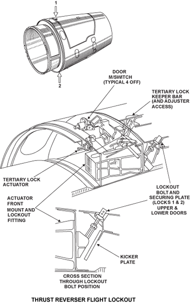
Thrust Reverser System Lock Out
To allow continued operation with an inoperative reverser, the reverser can be locked out as follows:
- Each door can be fixed in the closed position by an Inhibition Bolt. The bolt passes through a strengthened section at the front edge of the doors and screws into the actuators front mount fitting. When fitted, the bolt will protrude above the cowl surface and is red in color
- Further, the system can also be inhibited by use of the Manual Inhibit Lever, as described under the ICU Operation earlier
 \
\

System Indication
The four Stow switches, the two LVTs, and the ICU pressure switch have EEC channel A and B inputs, for deploy and stow sequencing and for flight deck indications. Indications are provided in the form of messages and icons displayed on the EICAS primary display.
The Thrust Reverser icons are in the inside of the N1 indicator. The icon displays in four different colors as follows:
- Green REV icon
- Thrust reverser deployed
- Thrust reverser deployed
- White REV icon
- Thrust reverser doors do not stow
- Thrust reverser doors do not stow
- Amber REV icon
- Thrust reverser doors in transit
- Thrust reverser doors in transit
- Red REV icon
- Inadvertent thrust reverser deployment with throttle in forward thrust range, engine will be commanded to idle
