


Overview
The function of the distribution system is to supply oil for lubrication to the engine bearings, gears and splines during engine operation. Oil also keeps the parts cool.
The distribution system supplies oil to the engine's internal drives/gears and bearings while the engine operates. It keeps the oil at the correct pressure, quantity and temperature. It also collects this oil and moves it back to the engine oil tank.
An oil cooler uses fuel to decrease the temperature of the oil. A secondary effect is that the fuel temperature stays in specified limits.
06/03/16
Oil Distribution
The function of the oil distribution system is to supply oil for lubrication, and then send it back to the tank.
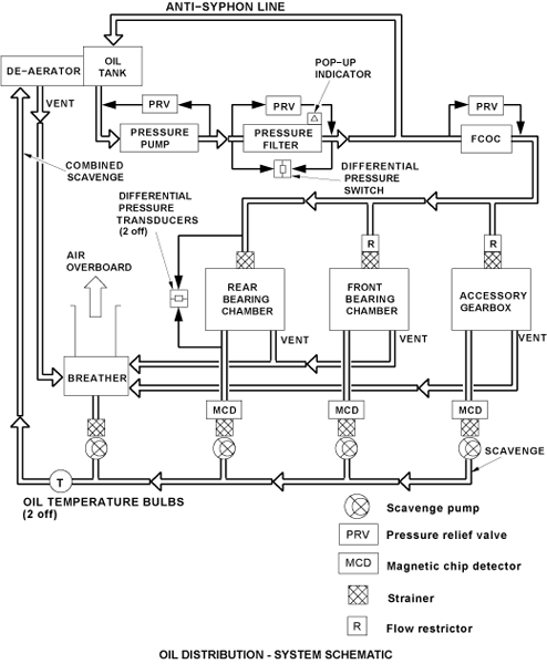
The oil distribution system is a full-flow recirculating type which is divided into a supply part and a scavenge part. The supply part includes a pressure pump which moves the oil through a pressure filter to the primary areas for lubrication. Pressurized oil is supplied to the front bearing chamber, the rear bearing chamber and the accessory gearbox. As the bearings and gears are lubricated, the oil collects in the primary areas. The oil is removed from these areas by scavenge pumps which send it back to the oil tank. There are magnetic chip detectors (MCDs) in the scavenge lines to monitor the internal condition of engine components.
The oil distribution system has the components that follow:
Oil Pump
The oil pump unit (OPU) supplies pressure to move the oil through the pressure lines to the drive gear and bearings, scavenges the oil as it flows out of these components and returns it, along with any foam (or trapped air) to the oil tank. The pump is installed on the rear face of the accessory gearbox (AGB).
The OPU contains one pressure and four scavenge vane-type elements arranged along two parallel shafts. This configuration is in a unit which is on the rear face of the accessory gearbox. One shaft is driven by the AGB, the other is connected to the first via a gear mechanism.
The pump has the following features:
- External connections for pressure feed (lube) and front bearing chamber scavenge
- Internal connections for breather, rear bearing chamber, accessory gearbox and combined scavenge
- Mounting for oil filter DP switches
- Magnetic chip detectors (MCDs) for FBC and RBC scavenge lines
- Oil pressure filter assembly
- An oil pressure-relief valve that opens at 424 psig
Pressure Filter Element
The pressure filter is a 30-micron filter element which is made of fiberglass. It is in a housing which attaches to the bottom of the oil pump unit. The lower part of the housing can be removed to give access to the filter element. Oil flows through an internal hole in the oil pump unit and through the filter element. It flows out through a different internal hole in the oil pump unit which has a non return valve. The filter element will remove contamination from the oil before it goes to the bearings and gears.
There is a bypass valve in the filter housing which lets the oil bypass the filter if the element has a blockage. This bypass valve also opens momentarily during an engine start on a very cold day. In the lower part of the filter housing there is a pressure-differential pop-out indicator. This operates at approximately 50 psi (344.74 kPa) when the filter becomes blocked. It gives a visual indication that the bypass valve has opened. But a bi-metallic strip prevents operation of the oil filter pop-up indicator at very low temperatures.
The oil filter pop-up indicator can only be reset when you remove the filter. It is not necessary to drain the assembly before removal of the filter. As the lower housing, and thus the element, are removed, a valve closes to prevent the leakage of oil. An oil filter differential-pressure switch also attaches to the oil pump unit. This gives a warning in the flight compartment when unwanted material starts to cause a blockage of the filter. The pressure switch senses filter inlet and outlet oil pressure and operates at a differential pressure of 18 psi (124.11 kPa).
Magnetic Chip Detectors and Scavenge Strainers
There are three MCDs in the scavenge side of the oil system. They are included in the scavenge lines from the front bearing chamber, the rear bearing chamber and the accessory gearbox. The MCDs, which can be removed and examined, collect ferro-magnetic particles in the oil. An analysis of the particles can give an estimate of component wear, and the condition of the engine.
The MCDs have threads and each is in a MCD housing. The housings attach to openings in the related scavenge line. In the openings there are also scavenge strainers. The MCDs for the front and rear bearing chambers are in the oil pump unit. The gearbox MCD is at the bottom of the rear face of the gearbox. The scavenge strainers can also be removed, examined and cleaned.


06/03/16
Oil Cooling
The primary function of the oil cooling system is to control the engine oil temperature in a specified range. Control of the oil temperature is necessary to supply the engine with sufficient cooling and lubrication.
During usual engine operation, unwanted engine heat is transmitted to the oil supply. The hot oil then goes to the fuel-cooled oil cooler. Here the unwanted heat in the oil is transmitted to the fuel. The heat management system controls the flow of oil to the fuel-cooled oil cooler, thus controls the fuel output temperature.
The engine electronic controller (EEC) controls the engine oil temperature and its heat transfer. The oil cooling system has the component that follows:
Fuel-Cooled Oil Cooler
The fuel cooled oil cooler (FCOC) is bolted directly on to the left side of the engine bypass duct. It enables the exchange of heat between engine fuel and oil, reducing the oil temperature, and heating the fuel to prevent the possible formation of ice crystals in the fuel.
The FCOC consists of two housings containing a removable core and a fuel filter cap. The housings, made of aluminum casting, provide an accommodation for both a core and a low-pressure fuel filter. The fuel filter cap has a pressure plate that maintains the fuel filter in the specified position. Details of the fuel filter and the two fuel temperature bulbs associated with this system. A drain plug is installed in the filter cap for maintenance procedures.
The FCOC has two bypass valves. One is an oil pressure-relief bypass valve for the core, set at 50 psid, and the other is a fuel filter bypass valve, set at 25 psid. The oil pressure-relief valve lets the oil bypass the fuel-cooled oil cooler during cold engine starts. The fuel filter bypass lets the fuel bypass the low pressure filter when it is clogged. An antisiphon hole is located between the oil inlet and outlet ports to prevent the oil from migrating after engine shutdown. A weep drain gives indication of a real failure between the fuel and the oil system.
