


Overview
The function of the oil indicating system is to give flight compartment indications of oil quantity, temperature and pressure. It is also to give an indication of pressure filter blockage.
The oil indicating system is divided into four different parts. The quantity of oil which the engine oil tank keeps is continuously monitored. This data goes to the engine electronic controller (EEC) and subsequently to the engine indication and crew alerting system (EICAS) for display in the flight compartment. There is also a visual display of the quantity of oil in the oil replenishment system.
A temperature transducer measures the oil temperature in the scavenge part of the oil system. This data goes to the flight compartment.
The oil pressure is measured as a differential pressure between the supply line and the scavenge line. Two transducers transmit the data to the EEC and the flight compartment. The flight compartment indication includes a warning if there is low oil pressure.
Oil-pressure filter blockage shows as an advisory indication in the flight compartment and as a visual indication at the filter. The visual indication occurs when the filter is fully blocked.
06/03/16
Engine Oil Quantity Transmitter
Caution:
You must do a check of the engine oil level between 5 and 30 minutes after the engine stops. If you do not obey these time limits, you can put too much oil in the oil system. Damage to the engine can occur if you put too much oil in the oil system.
The oil quantity transmitter is immersed in the main oil tank and sends out oil level signals to the respective electronic engine control (EEC). It is fitted in the oil tank towards the front of the lower tank face by means of two bolts and has a single O-ring seal at the oil tank interface.
The transmitter is a transducer consisting of a 15-resistor/reed switch stack, activated by a magnetic float which causes a magnetic field. The switches are usually open, but the magnetic field causes some to close when the float is sufficiently near. As the float moves up or down, two or three switches adjacent to the float close.
The output signal from the transmitter to the EEC is adjusted for two or three closed switches. The EEC converts these signals into an oil quantity value, and relays it to the oil replenishment system and as an oil quantity digital display at the status page. The oil quantity transmitter interfaces with channel A of the EEC only. The oil which goes to the system, and the attitude of the aircraft have an effect on the position of the float.


Airframe-Mounted Oil Tank Probe
The airframe-mounted oil tank probe is a capacitance type probe which is in the airframe-mounted oil tank. The airframe-mounted oil tank is in the aft equipment compartment of the aircraft. Its probe monitors the oil quantity and sends the data to the flight compartment. This shows on the EICAS display as a digital display. This probe is part of the oil replenishment system.

06/03/16
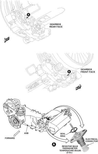
Oil Temperature Bulbs
Oil temperature in the scavenge line to the tank is measured with two temperature bulbs (resistive bulb thermometers or RBTs). One bulb is for each channel of the EEC, that vary their resistance with temperature changes.
The two temperature bulbs are positioned close to each other, in such a way as to be exposed to the same temperature. One is fitted to the front face of the AGB above the hydraulic pump and the VFG unit. The other bulb is mounted on the AGB rear face between the oil pump unit and the oil tank.
The system operates by using a constant current source to drive the resistance of the thermometer. The action produces a voltage that has to vary with the resistance to maintain the constant current. The EEC changes this data to a digital value and transmits it to the visual display in the flight compartment. This method enables good fault detection since an open circuit produces an unmistakable out-of-range voltage.

Oil Pressure Transducer
The oil pressure indicating system provides an indication of the pressure difference between the oil feed and the RBC scavenge line, and displays it at the bottom left corner of the EICAS primary page. The oil pressure transducers are located on the rear flange of the bypass duct, adjacent to the fuel drains tank.
The pressure differential is measured by two strain gauge type transducers. Each transducer is allotted to one of the EEC’s channels.
The transducers use an excitation voltage from the EEC, and employ it to produce an AC output. The magnitude of this output is proportional to the differential pressure. An electrical signal of this pressure is sent to the EEC.
The EEC compares the pressure against engine operating limits for low oil pressure. If the pressure falls below the minimum limit for continued engine operation, as long as rpm is > 56% N2, the EEC will trigger a red CAS warning message of L/R OIL LO PRESS on the EICAS primary page.
The minimum engine operating (or red line) limit for the oil system is 25 psi. The ground limits/inflight limits in the amber range are dependent on N2 RPM, and form part of the EEC schedules.

Oil Differential Pressure Transducers
There are two oil differential pressure transducers on the rear flange of the bypass duct near the fuel drains tank. They measure the pressure differential between the supply line pressure and the rear bearing chamber scavenge line pressure. The transducers, one for each channel of the EEC, use a voltage from the EEC to produce an AC output. This output is in proportion to the differential pressure.
The EEC uses the oil pressure value for the flight compartment display only. The EEC also compares the pressure measurement with the limits for low oil pressure continuously during engine operation. If the pressure decreases to less than the low limit, the EEC transmits a low oil-pressure warning to the flight compartment. A low pressure indication does not show if engine operation is below idle power.


06/03/16
Oil Filter Differential Pressure Switch
The oil filter differential pressure switch is on the oil pump unit. It monitors the differential pressure between the inlet and outlet sides of the pressure filter. As filter blockage starts to occur, the differential pressure increases to operate the switch. An advisory indication goes to the flight compartment when the differential pressure is more than 18 psi (124.11 kPa).
There is one filter differential pressure switch and it is connected to channel B of the EEC. The switch gives a blockage indication when the contacts are open. The EEC does not use this information for control functions, but gives an indication for maintenance functions. If the oil temperature is very low, the oil viscosity is sufficiently high to give a false indication of filter blockage. When this occurs, the blockage indication will not operate.


06/03/16
Oil Filter Differential Pressure Indicator
A bypass indicator on the oil pump unit provides a visual warning of impending filter blockage. The indicator is operated by differential pressure and is mounted at the bottom of the oil filter housing and is retained by a spiralox ring.
The DPI comprises an actuator piston with a visual indicator restrained in a housing by a magnet assembly which is subject to filter upstream and downstream pressure. A bimetallic strip serves to prevent the DPI operating at temperatures below 30 °C.
When the filter differential pressure rises to approximately 50 psi (344.74 kPa), the magnet assembly is forced away from the actuator piston the spring force on the piston causing it to pop out. A spring loaded steel ball will be forced between the magnetic armature and the actuator piston preventing the indicator from retracting after the differential pressure on the magnet assembly has decreased.
The pop out indicator will not retract until the DPI (and filter housing) have been removed from the oil pump unit and inverted. The steel ball will then reposition itself under the influence of gravity.

10/21/20
Component Location Index
| Component Location Index | |||
|---|---|---|---|
| IDENT | DESCRIPTION | LOCATION | IPC REF |
| C45 | AIRFRAME-MOUNTED OIL-TANK PROBE | ZONE(S) 310 | 79-31-02 [ GX ] [ GXRS ] [ G5000 ] |
| Component Location Index | |||
|---|---|---|---|
| IDENT | DESCRIPTION | LOCATION | EMM REF |
| - | ENGINE OIL-QUANTITY TRANSMITTER | ZONE(S) 400 | 79-31-01 |
| - | OIL DIFFERENTIAL-PRESSURE TRANSDUCER | ZONE(S) 400 | 79-33-01 |
| - | OIL-FILTER DIFFERENTIAL-PRESSURE SWITCH | ZONE(S) 400 | 79-34-01 |