


Overview
The purpose of the storage system is to keep the necessary quantity of oil for the engine.
The storage system has two systems to keep engine oil. It has the engine oil storage, which keeps the oil to lubricate and cool the engine bearings and gears. It also has the oil replenishment system, which keeps the oil to add it, as necessary to the components that follow:
- Left Engine Oil Tank
- Right Engine Oil Tank
- Auxiliary Power Unit (APU) Oil Tank
06/03/16
Engine Oil Storage
Oil for lubrication is contained in a main tank (or reservoir), located on the left side of the accessory gearbox (AGB), and forms an integral part of the AGB. The engine oil storage keeps 3.2 US gal (12.15 L) of engine oil in its oil tank and supplies the necessary oil to the engine pressure pump. The engine oil tank can be gravity filled or, if it is not full, the oil can be added from the airframe-mounted oil tank. The status page of the engine indicating and crew alerting system (EICAS) shows the oil quantity. It also gives a low oil level indication when the oil quantity in the tank is less than 75%. An aux (auxiliary) oil tank, formed by the cavity portion of the AGB, holds a smaller portion of the oil. An ejector system ensures the circulation of oil between the two tanks.
The oil tank is not a line replacement unit, as it is an integral part of the accessory gearbox. The major parts of the oil tank are:
- Oil level sight gauge (with graduations in U.S. pints and liters)
- Oil gravity and pressure-fill provisions
- Auxiliary oil tank feed ejector system
- A pressure-raising valve
- A deaerator
- A strainer at the oil supply outlet
After circulating through the engine, the combined return oil enters the tank and is passed through a spiral deaerator to reduce the level of foam in the tank. An accessory gearbox breather releases the unwanted air from the oil. Oil tank venting is achieved by an internal gearbox connection to the breather.
A restrictor in the vent pipe pressurizes the oil tank to 6 psig, ensuring adequate oil feed to the pressure pump at all engine operating conditions. An antisyphon line between the fuel cooled oil cooler (FCOC) and the oil tank prevents the oil from siphoning into the gearbox during engine shutdown. The flow is used to wash the area above the oil level in the sight glass to maintain a clear display.
The functions of the oil storage system are as follows:
- To contain the oil that is not used
- To give a sufficient supply of oil to the oil pump in all engine operation conditions
The oil level sight gauge/glass displays oil quantity in U.S. pints and liters up to slightly above the FULL mark, and has a line marking the minimum dispatch point, set at 10.62 ± 0.16 U.S. quarts. The tank may be gravity filled at the tank, or remotely filled from the oil replenishment tank in the tail compartment.
Gravity Oil Filler
The oil tank has a gravity oil filler to make it possible to manually fill the oil tank.
Pressure Oil Filler
It is possible to add oil to the oil tank from the airframe-mounted oil tank through a pressure oil filler.


06/03/16
Oil Replenishment System
The Oil Replenishment System is intended only for on-the-ground-replenishment when required, of the oil tank of each engine and the APU individually from a remotely located oil tank, using a control and display panel in the cockpit. It must be noted that this system is not intended for filling up an empty oil tank of an engine or the APU.
The selection is done from the OIL REPLENISHMENT control panel in the flight compartment behind the pilot's seat. The oil replenishment system keeps 1.5 US gal (5.7 L) of engine oil. The system operates only in the conditions that follow:
- The aircraft is on the ground (weight-on-wheels (WOW))
- The two engines are not in operation
- The applicable engine oil tank or the auxiliary power unit (APU) is not already full
- The airframe-mounted oil tank has a minimum oil quantity of 1.06 US qt (1.03 L)
The oil replenishment system has the components that follow:
- Controls and Displays
- Oil replenishment tank
- A replenishment pump
- An OIL REPLENISHMENT control panel
- A selector valve
- Oil Tank Probe
- An airframe-mounted oil-tank drain valve


Controls and Displays
The controls and displays of the oil replenishment system are arranged on the OIL REPLENISHMENT panel that is on the left side of the cockpit bulkhead at FS280.
APU/Engine Oil Tanks/Replenishment Reservoir Quantity Displays
Displays of oil quantities in the APU, the engine oil tanks and the oil replenishment reservoir are shown on the EICAS Status page. The engine and APU oil levels will only display when on the ground (weight on wheels) and when not running.
If oil quantity is normal in the respective oil tank, the digital readout on the EICAS primary page will be green in color. If oil quantity is < 3.0 U.S. quarts for > 10 minutes, a single chime will sound and the respective L/R OIL LO QTY caution message will flash on the EICAS primary page, accompanied by the two flashing Master Caution lights on the glareshield. The flashing actions above will continue until they are “acknowledged”, that is, until either light is pushed momentarily.
While no in-flight alerts are available if the APU/Replenishment Tank level is low, the following alerts are available on the ground, provided the PBA marked POWER on the Replenishment Panel is pushed in and latched and the white SYSTEM ON legend on this PBA is illuminated.
If the replenishment tank level is low (≤ 1.5 U.S. quarts), the oil quantity will turn amber in color on the status page. When the replenishment panel is energized, the green TANK LO legend on the lamp marked RESERVOIR will be turned on, and the RES LO OIL QTY (advisory) message will flash on the EICAS primary page.
If the APU tank is low, its oil quantity digital display will turn amber and flash, while the advisory message of APU OIL LO QTY, will appear and flash on the EICAS primary page. The APU oil replenishment green PBA marked LO OIL will also be turned on. As before, flashing will stop automatically, if not acknowledged within 5 seconds.
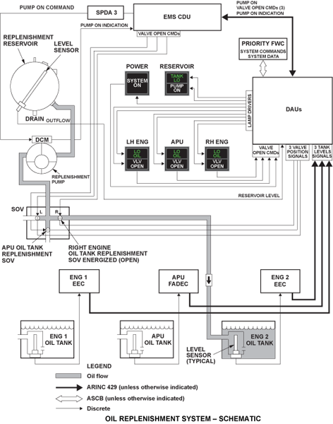
Fault Warning Computer
The fault warning computer (FWC) performs the following functions in the oil replenishment system:
- Monitor the system to verify when the transfer of oil is enabled by the EMS CDU
- Command the appropriate valve open and the pump on
- Drive lamp outputs, which in turn illuminate annunciators on the control panel, indicating which valve is open, the state of the pump, and the oil quantity levels
- Monitor the system for notification that the amount of oil transferred is sufficient
- Command the valve closed, the pump off, and extinguish the annunciator lamp outputs
Oil Replenishment Tank
This tank is mounted in the aft fuselage equipment bay (FS923.0). It is held in place by two clamps on two cradles and has a capacity of 6.0 U.S. quarts or 5.7 liters. The tank has an expansion space of 0.12 quarts of its full capacity, and a vent pipe at its top. An oil output port, an oil level probe, a vent at the top of the expansion space (which permits pressure to release at any normal flight condition), a drain valve at the bottom and a filler cap with an adapter are also parts of the reservoir. It has the components that follow:
Replenishment Pump
This pump is connected to the output port of the reservoir and in turn, has an output pipe to the selector valve. It is located in the fuselage rear equipment bay near the reservoir (FS911.25). The pump is driven by a 28 VDC motor with an oil supply line from the airframe-mounted oil tank and an output line to the selector valve and has a nominal flow capacity of 0.5 ± 0.25 gpm, at a pressure between 10 and 15 psig.
OIL REPLENISHMENT Control Panel
The OIL REPLENISHMENT control panel is installed in the flight compartment, on the left bulkhead (FS280.0). It has five two-legend switch/lights as follows:
- The SYSTEM ON two-legend switch/light has SYSTEM (top) and ON (bottom)
- The RESERVOIR two-legend switch/light has PUMP ON (top) and TANK LOW (bottom)
- The LH ENG two-legend switch/light has VALVE OPEN (top) and LOW OIL (bottom)
- APU two-legend switch/light has VALVE OPEN (top) and LOW OIL (bottom)
- RH ENG two- legend switch/light has VALVE OPEN (top) and LOW OIL (bottom)
To use the OIL REPLENISHMENT control panel, the aircraft must be on the ground (WOW condition). When you push the SYSTEM ON switch/light, all the switch/lights come on for a three-second lamp test. After three seconds, they go off (except the SYSTEM ON switch/light and the LOW OIL light for the tank of the engine that has less than 5 US qt (4.72 L) or for the APU that has less than 3.96 US qt (3.74 L)). You can then push the applicable switch/light, LH ENG, APU or RH ENG to start the oil replenishment procedure as follows:
- A signal goes to the load management system (LMS) which tells the selector valve to open to the right position
- The applicable VALVE OPEN light on the OIL REPLENISHMENT control panel comes on
- A signal goes to the LMS to make the replenishment pump come on
- The PUMP ON light comes on
The procedure to fill the applicable oil tank continues until one of the conditions that follows occurs:
- The applicable oil tank is full. Its LOW OIL light goes off
- The aircraft is weight-off-wheels
- The applicable engine or the APU starts
- The TANK LOW light for the airframe-mounted oil tank comes on
- The switch/light to fill the applicable oil tank is selected again
- The SYSTEM ON switch/light is pushed off
When the applicable oil tank is full, its LOW OIL light goes off. The LMS receives a signal to stop the oil replenishment pump. The PUMP ON light goes off. A signal goes to the LMS to close the selector valve. The VALVE OPEN light goes off.
If it is not necessary to do an oil replenishment for another engine/APU oil tank, you push the SYSTEM ON switch/light (and the oil replenishment system goes off). All switch/lights go off.

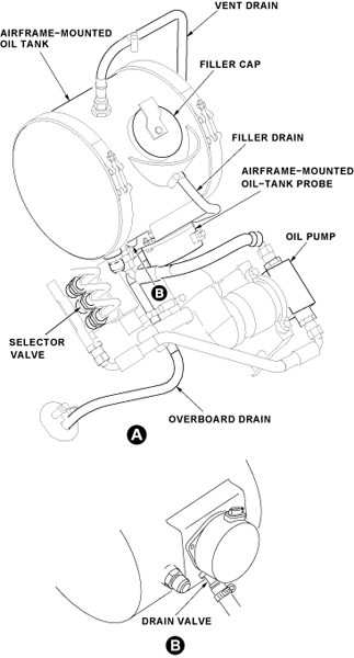
Selector Valve
This valve is located near the replenishment reservoir in the aft equipment compartment (FS911.25) adjacent to the airframe-mounted oil tank and is connected to the output line of the replenishment pump. The valve has 3 output ports: one for each engine oil tank, one for the APU oil tank. Each output port is kept closed by a spring-loaded solenoid valve. The solenoid must be energized to enable the associated valve to route the replenishment pump output to reach the selected engine or APU. An electrical interlock in the circuitry ensures that only one valve can be energized at any given time.
Oil Tank Probe
This oil replenishment tank-mounted probe is of the capacitance type. Its output is transmitted via the DAU, EICAS and EMS CDU interface to enable the tank quantity to be displayed as a digital readout on the EICAS Status Page, under the heading OIL QTY (QTS), at the designated space to the right of the white text marked RES. In the event of failure of the level probe, the digits will be replaced by amber dashes; the digits will be green if the oil level is normal, and white if low (below 1.5 U.S. quarts /1.42 liters).
Airframe-Mounted Oil-Tank Drain Valve
A push-type drain valve is installed at the bottom of the oil tank to drain the oil out of the tank.
Drain Mast
The drain mast is the outlet port for the aircraft that drains flammable residual fluids (oil, fuel and water) through a controlled drainage path to the ambient air. The drain mast is located below the aircraft fuselage from FS861.00 to FS877.25. The fluids tend to collect in different components of the engines, the fuel, the oil and the hydraulic systems.


06/01/20
System Operation
The conditions below must be valid for the oil replenishment system to function. If the conditions existing are acceptable to the integrated avionics computer (IAC) and if one of the PBAs marked LH/RH ENG or APU (on the replenishment panel) is momentarily pushed in by the operator, it will initiate and latch in the respective oil replenishment circuit.
The three PBAs are spring-loaded and will not latch in. Only one circuit can be energized in this manner at any point in time, to preclude the replenishment of more than one tank at the same time.
Prerequisites
Prerequisites for system operation are as follows:
- 28 VDC power available at the Battery Bus
- Airplane on the ground (Weight On Wheels)
- The replenishment operation is started from 5 to 30 minutes after shutdown in the case of engines (or at least 15 minutes after shutdown for the APU)
- Both engines not running for replenishing either engine oil tank
- APU not running if APU oil tank is to be replenished
- The respective Engine oil tank level must be less than 9.5 U.S. quarts
- The APU oil tank level must be less than 4.5 U.S. quarts
- The replenishment tank must have more than 1.5 U.S. quarts/1.42 liters of oil
- The quantity probes in both the replenishment reservoir and the tank to be replenished must be serviceable
- The PBA marked POWER must be pushed in and the PBA for the tank to be filled must be pushed momentarily, to latch its replenishment circuit. No other replenishment PBA should be pushed in until the selected tank is topped up
Replenishment Procedure
The replenishment procedure is as follows:
- Select battery master switch on
- Push in the POWER PBA and verify that the legends on all the PBAs are illuminated and stay on for 3 seconds
- At the end of this time, only the SYSTEM ON legend and the LO OIL legend of each of the three tanks which is less than full should remain on; all other legends must be off
- It must be noted that no replenishment system switch, legend or CAS message can function unless the POWER PBA is first pushed in
- At the end of this time, only the SYSTEM ON legend and the LO OIL legend of each of the three tanks which is less than full should remain on; all other legends must be off
- Push only one of the three momentary contact PBAs marked APU or LH/RH ENG as applicable to initiate a signal to latch the replenishment circuit of the associated tank
- The signal will be canceled automatically when the tank has been filled up or, if the crew released the latched in POWER PBA before the tank had reached its full level
- The crew input signal to replenish (initiated at the applicable PBA) is routed to the IAC via the DAU, which directs the applicable port alone on the selector valve to be opened, and signals the replenishment pump to be started
- The status of the selected valve and the pump are transmitted via the DAU and the IAC to the EICAS for display at the replenishment panel
- Verify that the PUMP ON light and the applicable VLV OPEN light are both on, and that in a short time, the respective LO OIL light goes off to indicate that the associated tank is now full
- The IAC receives a signal from the respective tank level sensor; as soon as the tank is full, at this point, it turns off the replenishment pump
- Verify that the PUMP ON light and the applicable VLV OPEN light go out; this notifies the operator that the replenishment command signal initiated from the PBA has been automatically turned off
- Repeat the above procedure as necessary to fill up the other tank/s, one at a time
- If the TANK LO legend on the light marked RESERVOIR should come on at any time, the reservoir has to be refilled to reach more than one third of its full level before the IAC will permit any replenishment action to proceed further
Oil Level Readings and Oil Filling Characteristics
Oil Level Reading on the Sight Glass
The most precise method to determine the oil volume in the engine oil tank is by checking the oil level sight glass located on the upper oil tank. The indication plate features a hatched FULL band. The engine oil tank is full when the oil level can be seen within this band, provided the oil level check is done.
The oil level must not be above the FULL band. If it should be above the FULL band, the excessive oil volume must be drained from the upper oil tank.
Also, the cause for this malfunction must be found. If the oil level is below the FULL band, the amount of usable oil and hence the maximum flight range is reduced. However, if the electronic oil level reading system functions as designed, the oil level will always be within the FULL band.
The lower FULL level corresponds to an oil volume in the engine oil tank of 10.62 ± 0.16 U.S. quarts (10.05 ± 0.15 liters). The upper FULL level corresponds to 11.89 ± 0.16 U.S. quarts (11.25 ± 0.15 liters). The tolerance of ± 0.16 U.S. quarts (± 0.15 liters) is due to deviations of the casting geometry inside the engine oil tank and is applicable throughout the entire reading range of the sight glass.
The markings below the FULL band indicate how much oil must be added to get to the lower FULL level. The lowest mark corresponds to an oil level in the gearbox of 9.30 ± 0.16 U.S. quarts (8.8 ± 0.15 liters).
Because the sight glass is installed at the rear part of the engine oil tank, the accuracy is influenced by the aircraft inclination, e.g. due to uneven ground, incorrect tire pressure, etc. 1 degree of aircraft nosedown or noseup inclination leads to oil level misreading of approximately 0.3 U.S. quarts. It must therefore be ensured that the aircraft is parked on horizontal ground and that aircraft weight distribution and the tire pressure is correct when the sight glass level is read (Note: Bombardier defines the nominal engine inclination with reference to the horizon to be 3.97 degrees noseup).
Electronic Oil Level Reading
The electronic oil level reading delivers the signals for the EICAS indication, the control of the remote oil replenishment pump in the back of the aircraft and the low oil level warning light. The oil level is detected by an oil level sensor which is installed at the bottom of the upper engine oil tank. This sensor is a reed-switch type. This means that the sensor does not read linearly but in incremental steps. Considering the installation angle of the sensor, the distance between two adjacent reed switches is 0.21 inches with respect to filling height. Considering the upper oil tank calibration (filled oil volume vs. filling height), the average resolution of the oil level sensor within the reading range of the oil level sight glass is 0.43 U.S. quarts (0.41 liters).
Oil Filling Characteristic
The engine oil tank of the BR700-710 engine consists of two portions, the upper and lower oil tank. Both tanks are integral parts of the accessory gearbox which is a magnesium casting. The capacity of the lower oil tank is approximately 3.7 U.S. quarts (3.5 liters). The upper oil tank holds approximately 8.5 U.S. quarts (8.0 liters). When the engine is running, an ejector pump continuously empties the lower into the upper oil tank from where the engine oil supply is drawn.
The two oil tanks are connected by two stack pipes. The lower stack pipe routes the oil from the upper into the lower oil tank, provided the filling height in the upper oil tank is enough to submerge the orifice of the lower stack pipe. There is no other way to fill oil into the lower oil tank. The upper stack pipe vents the lower into the upper oil tank and does not have any influence on oil filling or engine operation characteristics.
The arrangement of oil tanks leads to a nonlinear oil level reading When a completely drained gearbox is refilled with oil, the level rises on the oil level sight glass as soon as it reaches the reading gauge. After having filled approximately 5.3 U.S. quarts (5.0 liters) of oil into the upper oil tank, the oil level stops rising on both the sight glass and the oil level sensor, although more oil can be added. After having filled approximately 9.0 U.S. quarts (8.5 liters) in total, the lower oil tank is completely full, and the oil level continues to rise in the upper tank. This is indicated on the sight glass and the oil level sensor. During engine operation when oil is consumed, the same process happens in the opposite direction.
Since the content of the lower oil tank cannot be reliably detected, the engine oil tank only contains an adequate volume of oil, if it is serviced to FULL.


Particular EEC Oil Level Signals
Beside the normal oil level reading, the engine EEC also provides the following signals with regard to the engine oil tank level:
- If the oil volume in the engine oil tank falls below 9.5 U.S. quarts (10.3 l), the EEC provides a signal bit which allows the remote oil replenishment to be engaged (provided the aircraft is on ground and the engine has been shut down for at least 5 minutes)
- If the oil level reaches this point during remote oil replenishment, the replenishment pump is shut off in order to prevent engine overservicing
- If the oil level is already above this point when the remote oil replenishment system is activated, the replenishment pump would not be switched on
- If the oil level reaches this point during remote oil replenishment, the replenishment pump is shut off in order to prevent engine overservicing
- If the oil quantity as indicated by the EICAS falls below 3.0 U.S. quarts (2.8 liters) for more than 10 minutes, and the engine is running, the EEC triggers a low oil level caution EICAS indication.
Usable Oil Quantities
6.41 U.S. quarts (6.07 liters) of the engine oil content cannot be consumed by the engine (unusable oil quantity) because it is required to lubricate the engine or it is hidden in pipes, the oil cooler etc. Considering the worst-case casting tolerance of the accessory gearbox, the minimum usable oil quantity is 4.05 U.S. quarts (3.83 liters) when the engine was serviced to the lower FULL mark. The maximum allowed oil consumption of the engine is 0.2 liters per hour. This leads to a flight duration of 19.15 hours within which the aircraft can be operated throughout the whole attitude envelope without adversely affecting the engine oil supply. If the engine is serviced and operated correctly, the low oil level caution is never reached.
