


Overview
The function of the engine starting system is to turn the engine sufficiently for an engine start.
The engine starting system uses high pressure air to supply the power which turns the engine. This air source can be the ground supply, the auxiliary power unit (APU) or the adjacent engine which operates. The high pressure air is supplied through airframe/engine environmental control system (ECS) ducts to the starter air valve. When this valve opens, the air goes through a starter air duct to the air turbine starter. As the starter turns, the movement is transmitted through a gear train and clutch mechanism to an output shaft. The output shaft engages with the accessory gearbox radial drive shaft to turn the HP compressor rotor.

06/03/16
Starter Motor
The starter is a pneumatically-operated turbine unit. The starter motor drives the HP Compressor shaft assembly via the starter drive gear in the AGB, to enable engine starts. The starter mounting adapter is doweled and bolted to the accessory gearbox front face.
A V-band clamp and dowel attach the starter to the adapter on the gearbox. A V-band clamp is used to attach ducting to the starter.
The starter assembly weighs approximately 23 pounds and has the following features:
- A self-contained oil system
- An oil pump driven by output drive shaft with a shear neck
- An oil filler and level indicator plug, and
- A Magnetic Chip Detector (MCD)
When a new starter is installed or if the starter oil is drained and refilled, the oil should be topped up to the level of the filler port on the starter. Use the same oil as the engine oil type.
Caution:
Protective gloves should be worn to avoid injury when working on the SAV/STARTER ducts. If the SAV is to be manually opened in order to dispatch the airplane with a faulty SAV, starter exhaust air of up to 200 °C will exit overboard via the open SAV access panel on the lower cowl.
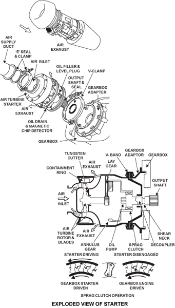
Internal Features
The internal features of the pneumatic starter motor are as follows:
- A single-stage air turbine
- A turbine failure containment ring
- A tungsten cutter to cut off turbine disc/blades for bearing failures, and
- Reduction gear
- Ring gear and hub assembly
- A sprag-type clutch drive to output shaft
- Output shaft decoupler
These components are assembled in a casing which includes a containment ring, an air inlet and air outlets.
An output drive shaft decoupler eliminates the possibility of driving the turbine wheel, should the sprag clutch seize up. An output drive shaft shear neck protects the accessory gearbox from damage, in the event of starter turbine over torque or unit seizure.
Air from the aircraft pneumatic system, routed through the SAV, flows through the starters nozzle guide vanes to drive its turbine, and is discharged thereafter, into the area inside the cowl, through the starters outer casing. This air is exhausted overboard through grills in the cowl.
The turbine in the starter drives an annular gear through three layshafts (or planet gears). The turbine rotor turns a high-speed pinion gear which engages with three planetary gears. These planetary gears, which together are the reduction gear assembly, change the output from the starter turbine rotor. A high-speed low torque intput becomes a low speed high torque output. The annular gear, in turn, drives the starter output drive shaft through a sprag type clutch.
As the ring gear and hub assembly turns, the outer race of the clutch mechanism also turns. This causes the sprags to lock with the inner race and thus engage the clutch to turn the output shaft. The starter output shaft engages with the accessory-gearbox radial drive-shaft which turns the HP compressor rotor. The starter increases the speed of the HP rotor until it is sufficient for the engine to be started. When the HP compressor speed is at a set limit, the compressor continues to turn without the aid of the starter.
At starter cut out speed (at 42% N2 as sensed by the EEC), the SAV is closed, the turbine loses speed causing the sprag-clutch to disengage. The turbine wheel runs down to zero rpm while the output drive continues to rotate with the gearbox. An anti-lock device prevents the movement of the sprags into the engaged position when the clutch is disengaged. In this condition, there is an oil film in the clearances between the sprags and the inner and outer races. If there is a failure of the sprag clutch, an output shaft decoupler disengages the starter turbine rotor.

06/03/16
Starter Drive Adapter
The starter drive adapter has the shape of a small cone which has a mating surface behind a smaller diameter front flange. There are eight holes at equal distance around the outer circumference of the mating surface. The area around each of these holes is made stronger. Between two of the top holes, there is a dowel position. This is to make sure the starter drive adapter is installed in the correct position.
The starter drive adapter is installed on the front face of the accessory gearbox at the starter mounting pad. The holes in the mating surface align with studs in the gearbox front face. It attaches with nuts. The function of the front flange of the starter drive adapter is to install the air turbine starter. There are dowels on the inner edge of the flange for the correct installation of the starter. The starter attaches to the starter drive adapter with a V-band coupling.
06/03/16
Starter Air Valve
The starter air valve is a butterfly-type shutoff valve which operates pneumatically. It controls the flow of air to the air turbine starter. The valve is near the bottom rear of the engine between the starter air duct and the cabin air duct. When you set the start sequence on the ENGINE control panel in the flight compartment, the engine electronic controller (EEC) causes the valve to open. The starter air valve includes the components that follow:
- A butterfly valve
- A dual-coil solenoid control valve
- A dual-pole microswitch
- A manual override feature, and
- A visual valve position indicator
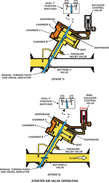
The butterfly valve operates in a cylindrical housing. It aligns with, and is installed between, the air ducts. It attaches to a shaft which is installed through the diameter of the housing and turns on bushings. There is a seal ring on the butterfly valve to keep air leakage to a minimum. One end of the shaft comes out of the housing in the shape of a square drive. This square drive can be turned manually to operate the valve if there is an electrical failure. The other end of the shaft goes through the valve and actuator assembly and gives a visual indication of the valve position.
The butterfly valve operates with a pneumatic actuator and a solenoid valve. The butterfly valve is operated by the balance of forces between a built-in torsion spring and differential air pressures in the SAV chambers as controlled by the solenoid valve. These are in a valve and actuator housing which attaches to the cylindrical housing. The pneumatic actuator has two diaphragms of different surface areas which attach to the opposite ends of a piston. A torque lever attaches the piston to the butterfly valve shaft. When the actuator moves, the torque lever turns the shaft to open or close the butterfly valve. A torsion spring keeps the valve in the closed position.
The solenoid valve contains a ball valve, a spring loaded plunger and an electrically-operated solenoid. The solenoid has two coils (one connects to channel A and the other to channel B of the EEC). These coils are usually energized together but can also operate the solenoid independently. When the solenoid is energized, the ball valve is set so that the actuator can move to the open position. Heat goes to the solenoid valve by a small pneumatic bleed flow. This prevents a malfunction of the valve in conditions where it is possible for the valve to freeze. Air comes from immediately upstream of the butterfly valve and goes through a regulator orifice.
When either solenoid is energized by an input from one of the two EEC channels, air is ported to chambers A and B. Chamber C is now vented to atmosphere via the adjustable vent. Pressure in chamber B now overcomes the torsion spring load to force the piston to open the butterfly valve allowing air flow to the starter motor. Chamber C venting is controlled by the vent to a preset opening rate of the valve. This controlled vent rate prevents shock loading of the starter motor.
When the pressure in chamber A and B is more than the pressure in chamber C plus the torsion spring, the actuator moves. This causes the valve shaft to turn and the butterfly valve to open. As the valve shaft starts to turn, microswitches on the actuator housing close. These send an indication to the EEC that the starter air valve is open. There is also an indication on the engine indication and crew alerting system (EICAS).
When both the solenoids are not energized, air is ported to chambers A, B and C. Air pressure differential loading, combined with the load of the torsion spring, which is directed towards the close position, forces the piston to drive the butterfly valve closed. The microswitches on the housing open and send an indication to the EEC that the valve is closed. There is also an indication on the EICAS. In the absence of bleed air, or if power to the solenoid is lost, the SAV will be spring-driven to the fail-safe closed position.
The solenoid control valve is heated by upstream air to prevent ice formation and subsequent valve malfunction. The SAV also includes a pressure relief valve for protection in case the duct pressure rises above normal value.
A pressure failure to the SAV, due to a ruptured diaphragm, will cause the torsion spring to drive the SAV to the closed position. If the SAV fails as above, in order to enable dispatching the aircraft, the valve can be held open manually for the duration of the next start(s) on that engine.
In case of loss of electrical power to the solenoids, the SAV closes. This is considered to be a "fail safe" position.


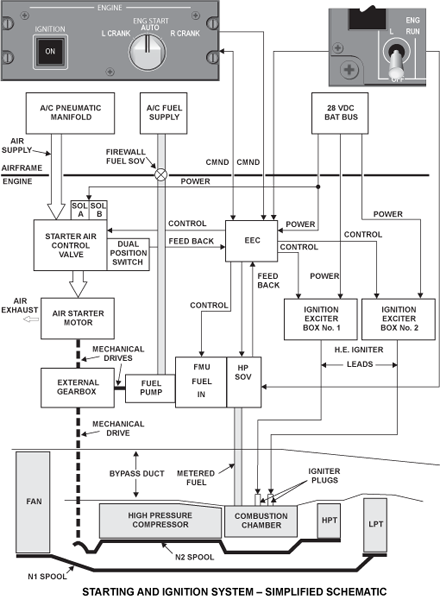
Starter Air Valve Control
The SAV is controlled from pilot input, via either channel of the EEC, depending on the mode of operation and as per the applicable EEC program.
During automatic ground starts, upon command from the respective ENGINE RUN switch, the EEC will initiate engine rotation, supply fuel and ignition at the right points in the start cycle, and monitor engine parameters throughout the start. The EEC will also close the SAV, disengaging the starter motor, and switch off ignition at the proper time.
During manual ground starts, opening and closing of the SAV and the HPSOV are controlled by the pilot. The EEC will control the switching on and off of the igniters and closing the SAV. Commands from either EEC channel can control the SAV. Pilot input is from the ENG START switch on the ENGINE panel, and comprises the "high side switch" of the circuitry. The "low side switch" is provided inside the EEC.
The start air valve (SAV) is designed to be slow to open and close during operation. This reduces loads on the starter and sudden thermal increase/decrease on the APU, EGT.
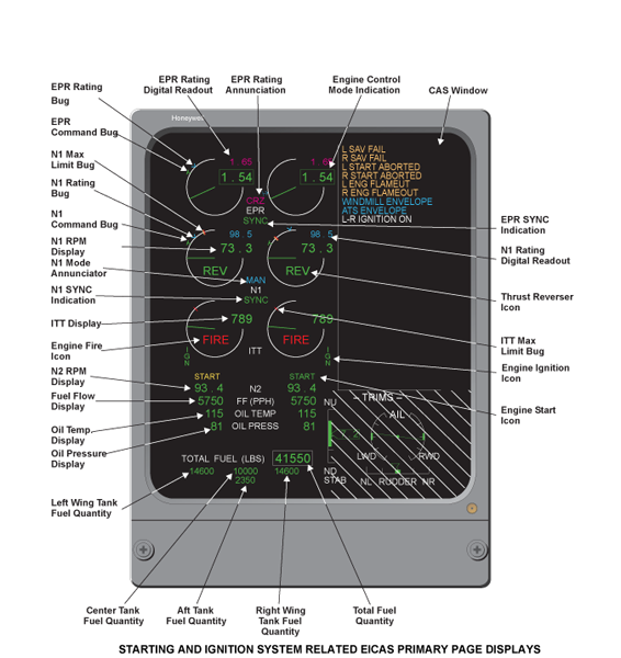
The SAV moves away from the closed position during a start. If signals from both the microswitches indicate to the EEC circuitry that the valve is not closed, the EEC will initiate commands (via the ARINC 429 communication bus and the associated IAC), to display the START icon on the EICAS primary page. This icon will be displayed just above the respective engines N2 digital readout, until the valve is closed again.

06/03/16
Starter Air Duct
The starter air duct is in two parts which connect together with a V-band coupling. It is installed along the lower right side of the engine. At the rear, the duct attaches to the starter air valve, and at the front, to the air turbine starter. The mating flanges of this installation also connect with V-band couplings. There are E-type seals between the mating flanges which prevent air leakage at the joints.
Two brackets are welded to the starter air duct near the center point. In an adjacent position on the bypass duct, there are two support brackets. Rods are installed between each duct bracket and the opposite support bracket to hold the air duct in position. There are three gimbal joints, two on the shorter front part, and one on the rear. These give the duct some movement which can occur when hot pressurized air flows through it.
System Operation
Since some of these modes differ between in-flight and ground operations of the aircraft, a WOW discrete signal is provided to the system, via the IAC and ARINC 429 bus. The EEC will revert or "default" to the inflight condition if the WOW signal is lost. Unless specifically noted otherwise, it is assumed that all other switches and controls are positioned properly for engine start.
Limitations
| Maximum Prestart ITT | 150 °C |
|---|---|
| Maximum ITT during start | 700 °C (during ground starts only) |
| Maximum time to reach idle | 120 seconds |
| ATS Duty Cycle | 3 consecutive start attempts of 180 seconds each, with a cooling interval of 15 seconds |
| Maximum rpm for Starter Reengagement | 42% N2 |
| Rotor Bow Limitation | As discussed earlier |
| Prestart Minimum Oil Temperature | -40 °C |
Rotor Bow Avoidance
If the BR710-710A2-20 series engine is to be started between 20 minutes and 5 hours after the previous shutdown, there is a potential for high core vibration during the next start. This is known as the Rotor Bow, which occurs due to differential cooling of the high pressure spool and subsequent distortions of the rotating assembly.
In all manual ground starts, the operator must carry out an "Extended Dry Crank/EDC" procedure, consisting of dry motoring the engine prior to start, for a minimum of 30 seconds at the maximum motoring speed achievable.
However, during all automatic starts, the EEC will determine if the EDC procedure is required, and carry it out automatically. In both manual and automatic starts, it is permissible to continue the starting operation immediately following the EDC procedure, without performing a spool down of the engine.
Automatic Ground Start
This is the engine starting mode normally used by flight crew on the ground, in which the engine functions and temperature (ITT) limits are monitored and controlled by the EEC. In addition, the EDC maneuver is automatically performed by the EEC, where necessary. In this mode, control of the starter, fuel and ignition is automatic.
Initial switch/control positions and aircraft/engine Status:
Engine is not running and airplane is on the ground (with WOW).
| ENG START Selector | AUTO |
|---|---|
| IGNITION Switch | NORMAL (not selected) |
| ENGINE RUN Switch | OFF |
| THROTTLE Lever | IDLE |
Start Sequence
The start sequence for automatic ground starts is as follows:
- Operator selects ENG RUN switch to ON
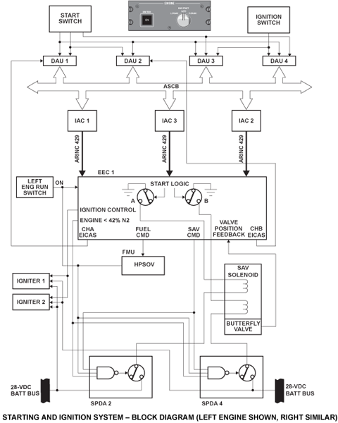
- The EEC initiates an automatic start by sending the proper signals to the start circuitry
- As a result, aircraft Battery Bus power is applied to the SAV solenoids via two of the independent SPDAs. The SAV opens in response
- The EEC uses the SAV position feedback to recognize that the SAV is open and initiates a signal to the IAC for the respective green START icon to be displayed during the time the SAV is open. (This icon appears as a horizontal line of text below the engines ITT gauge and above the N2 digital readout)
- If the SAV fails in position or disagrees with the command signal during or after the start, the START icon will turn amber. In addition, the EEC will cause the amber EICAS message reading L/R ENG SAV FAIL to be displayed in the CAS window. The EEC continues to monitor the engine and aborts the start
- If the EEC determines through its Non-Volatile Memory (NVM) that the critical "rotor bow" time window is not applicable for the current start, it will not carry out the Extended Dry Crank (EDC) procedure for that start
- If the EEC recognizes that the start being initiated falls within the critical "rotor bow" time window, it will first conduct the EDC procedure automatically and continue next with an autostart of the engine
- If, at the time of the start, the EEC is unable to determine the rotor bow time window due to lack of data or for any other reason, it will still perform the EDC procedure, prior to continuing with the auto-start of the engine
- The EEC turns ON the ignition at the appropriate time, and initiates a signal to the IAC for displaying the respective green IGN icon throughout the time ignition is maintained on the engine. (This icon appears vertically at the bottom outboard side of the applicable ITT gauge)
- The EEC sends out command signals to the FMU to open the HPSOV at 15% N2 rpm, and schedules fuel flow to achieve engine light up
- At 42% N2 rpm, the EEC deactivates the SAV and ignition circuits, and the respective START and IGN icons are canceled
- After lightoff, the EEC continues to check and control the FMU torquemotor, to promote smooth engine acceleration at a prescheduled rate, until it reaches idle rpm, (at approximately 62% N2), without undue rise in the ITT
- During all automatic starts, the EEC performs all the relevant checks for any starting abnormalities. If any critical abnormality is detected, the EEC will abort the start and initiate the display of the respective amber message reading L/R START ABORTED on the EICAS primary page
This message however, will not be displayed in case the operator turns the ENGINE RUN switch to OFF prior to an automatic start abort. It must be noted that if both igniters are faulty, leading to 2 consecutive automatic start aborts, the amber CAS message of L/R FADEC FAIL will also be displayed.
Manual Ground Start
This mode is used on the ground, usually when the operator wishes to control the start sequence and/or monitor some specific detail of the starting operation. Starter, fuel, and ignition are controlled by the EEC upon commands from the cockpit. However, the EEC will not perform the EDC procedure if applicable, or protect against exceedance of the engine’s ITT limit.
Initial switch/control positions and aircraft/engine status
Airplane is on the ground, (WOW) and the applicable engine is not running.
| ENG START Selector | AUTO |
|---|---|
| IGNITION Switch | NORMAL (not selected) |
| ENGINE RUN Switch | OFF |
| THROTTLE Lever | IDLE |
Start Sequence
The start sequence for manual ground start is as follows:
Note 1:
In manual starts, the EEC will not limit the ITT of the engine and the operator must closely monitor the ITT and abort the start where necessary. The operator must also avoid reengaging the starter above 42% N2 rpm.
Note 2:
In case of any critical abnormalities during this type of start, the operator must abort the start by moving the ENGINE RUN switch to OFF. In case of a hot, hung or wet start, or, if critical, the IGNITION PBA should also be selected off.
Note 3:
If the start is to take place in the rotor bow time window, the operator must proceed with a dry crank of the engine for a minimum of thirty (30) seconds, which may directly be followed with the start, without any pause for the engine to spool down.
Procedure
The procedure for manual ground start is as follows:
- Operator pushes the IGNITION PBA
- The EEC will turn on both igniters of both engines
- An IGN icon will be displayed below the outboard side of each ITT gauge
- The white ON legend on the PBA will be illuminated
- Operator moves ENG START selector to L CRANK/R CRANK as desired
- The aircraft power management system switches power on to the SAV solenoid of the respective engine, and transmits a "crank command" signal to the EEC
- The ignition for the other engine is ON continuous, if engine is running, and OFF after 30 seconds if engine is not running
- The EEC turns the ignition off on the cranking engine
- The EEC switches the path to ground of the SAV solenoid
- As a result, the SAV energizes
- The butterfly valve directs air to the starter
- The resulting starter torque turns the engine
- As the engine accelerates, at 20% N2, the operator selects the ENGINE RUN switch to ON
- The EEC reroutes ignition power to both ignition exciters of the engine being started. The IGN icon of that engine appears
- The fuel HPSOV opens and the EEC schedules fuel flow to achieve lightoff, and then controls engine acceleration until the engine stabilizes at idle (approximately 62% N2)
- The EEC turns off the SAV when N2 reaches approximately 42%
- The manual ground start sequence above is concluded by moving the ENGINE START selector to AUTO, and the IGNITION PBA to its off/"default" position. The ON legend on the IGNITION PBA and the IGN icon is canceled
Automatic Air Starts and In Flight Start Envelopes
The automatic air start is the normal engine starting mode in flight in which the engine limits and functions are monitored and controlled by the EEC. Control of fuel, starter and ignition is automatic, once the ENGINE RUN switch has been manually selected to ON.
The EEC will first determine from the IAS/Mach No. and altitude of the airplane, as well as the applicable engine´s N2 rpm, whether a "Windmill Start" can be accomplished or a "Starter – Assisted Start" (that is, if assistance from the starter) is required. Unless N2 rpm is 8% or more, the EEC will not decide on a windmill start.
The EEC will also send out signals to initiate an advisory message of either a WINDMILL ENVELOPE or an ATS ENVELOPE as applicable, on the EICAS primary page. Further, it will accomplish the type of engine start chosen, while monitoring and controlling the engine parameters.

Initial switch/control positions and aircraft/engine status
Airplane is airborne (W off W), and applicable engine is windmilling.
| ENG START Selector | AUTO |
|---|---|
| IGNITION Switch | NORMAL (not selected) |
| ENGINE RUN Switch | OFF |
| THROTTLE Lever | IDLE |
Start Sequence
The start sequence for automatic air starts is as follows:
- If the engines N2 rpm is 42% or more, the EEC decides on a "windmill start". If engine N2 RPM is less than 42%, a "starter-assisted start" is initiated. It also initiates the signals to the aircraft system computers to display the corresponding advisory (cyan) message reading WINDMILL ENVELOPE, or ATS ENVELOPE in the CAS window
- Operator moves the ENGINE RUN switch to ON
- The EEC will not initiate any commands to open the SAV if it is to be a windmill start. In the case of a starter-assisted start, the EEC will send out appropriate commands to open the SAV; in both cases, it will energize ignition and continue the start further, as in the case of an auto ground start
- If the engine is in the starter-assisted mode of operation, at the predetermined rpm, the starter and ignition are cut off automatically. In the case of a windmill start, the ignition alone is cut off at the appropriate rpm
- Control and monitoring of the engine to achieve smooth acceleration and a stabilized idle rpm are as before, carried out by the EEC
Manual Air Start
This is a starter assisted engine starting mode in flight, manually initiated by the pilot. The EEC does not limit ITT in this mode, but protects against engagement of the starter above the starter reengagement speed of 42% N2 rpm.
Auto-Relight
This type of relight is performed automatically by the EEC by turning on both igniters and fuel to the applicable engine and by simultaneously monitoring and controlling it, so as to restore it to normal operation. This mode of operation occurs only, if the flameout (or near flameout) of the engine is identified by the EEC through certain specific patterns listed below:
- The engine’s N2 rpm is be at or above idle
- The EEC determines engine flameout by the rate of change of N2, the threshold for the rate of change to qualify as one being a function of airplane altitude and P30. A deceleration rate greater than the threshold rate is identified by the EEC as a flameout and an automatic relight procedure is initiated immediately
- Alternately, the EEC detects a flameout by monitoring the difference between idle N2 rpm commanded and the actual idle N2 rpm achieved. If this difference is greater than a prescheduled threshold in its circuitry, the EEC assumes the condition as a flameout, and initiates an auto-relight procedure without delay. However, this process may be suppressed by the EEC for up to 15 seconds, if it occurred at the end of a transition from a low idle to a high idle
Upon detecting an actual relight at the end of the above, the EEC keeps both the igniters energized for a period of 20 seconds.
However, if the engine does not relight, the EEC will close the HPSOV at 35% N2, deenergize the igniters and initiate applicable commands for the display of the amber EICAS message reading L/R ENG FLAMEOUT on the primary page. The message may be canceled by moving the ENGINE RUN switch to OFF.
Continuous Ignition
This mode is manually selected when the pilot depresses the IGNITION PBA, in flight or on the ground, and automatically in flight, by certain airplane systems such as the stall protection system. This mode is not time-limited, but will reduce overall igniter life.
Quick Relight
The "Quick Relight" mode is activated automatically in flight only, if the engine is windmilling at or above idle rpm and the EEC detects the crew switching the ENGINE RUN switch from OFF to ON within 30 seconds from the time it was switched OFF.
The EEC responds by turning on fuel and both igniters to the applicable engine, and controlling fuel flow in an effort to stabilize the engine within the operating range. Under these conditions, if the engine rpm continues to drop below idle speed, the quick relight function will remain activated for up to 20 seconds, with continuous ignition.
If, however, the engine does not recover and continues to run down, then the EEC will close the HPSOV at 35% N2 and deenergize the igniters simultaneously. The crew may also deactivate the auto relight feature any time by turning the ENGINE RUN switch to OFF.
Control and Displays
The starting and ignition system uses the following to control the engines:
- Two throttle levers and two ENGINE RUN switches on the center pedestal
- An IGNITION PBA and an ENG START switch on the Engine Start module of the overhead panel
Cockpit displays of the system consist of a white ON light on the IGNITION PBA and several EICAS primary page indications such as EPR, N1, ITT, and N2, as well as two "icons" below the ITT gauges reading IGNITION and START.


ENGINE RUN Switches
The ENGINE RUN switches are a pair of two position, locking toggle type of switches, located aft of the throttle quadrant, one per engine, with ON and OFF positions.
These switches are positioned at a point determined by the operator, during engine start/shutdown/crank operations. Depending on the specific operational mode, each switch interfaces with/bypasses the respective EEC to initiate commands for the opening or closing of the respective engine’s high pressure (fuel) shutoff valve.
The functions of each ENGINE RUN switch are as follows:
- In the ON position, the HPSOV opens
- In the OFF position, the HPSOV closes
- During an automatic engine ground/air start, if the switch is in the ON position, it arms the appropriate EEC circuitry, which opens the HPSOV, under the proper conditions
- During a manual engine ground/air start, or a wet crank, if the switch is ON, it directly commands the EEC to open the HPSOV
- The ON command of the switch is overridden by the EEC to close the HPSOV
- In an overspeed, or
- During the abort of an autorelight, or
- During the abort of an automatic start
- The transition of the switch from ON to OFF initiates a reset of both channels of the EEC of the associated engine
- The transition of the switch from OFF to ON sends an output to the airframe to command the DC power (located in the associated SPDAs) for the solenoids of the SAV and to provide signals to the fuel distribution system for fuel pump operation
Each switch sends out discrete signals to each channel of its EEC via dedicated "high-integrity" double wiring. One of these signals informs the EEC of the switch position, using an open circuit to denote ON, and a closed circuit for OFF.
The EEC uses the other signal to reset its circuitry whenever the switch is moved to OFF, and to command the FMV/fuel metering valve to move to the "minimum stop" position. This enables a positive shutdown by providing the engine with a second means of closing the HPSOV hydraulically (using fuel pressure) via the FMV shuttle valve.
ENGINE START Selector
The ENGINE START selector is a rotary switch located on the engine control panel, on the overhead panel. It is used to send out commands of the desired mode of start/ignition, for either or both engines. It also provides the command for the SAV solenoid coils. The selector position is transmitted to the EEC via the IAC and the ARINC 429 bus. The selector has the following positions:
- L/R CRANK – generates EEC crank commands for the left/right engine for wet/dry cranking/manual starting
- AUTO – arms the EEC circuitry for automatic starting of both engines
Engine Shutdown
The normal procedure for an engine shutdown is as follows:
- The engine manufacturer (RRD) recommends that the engine be allowed to cool down at idle for three minutes prior to engine shutdown, with credit being applied to any taxi period just before shutdown. Operators will first satisfy the above condition
- Operator moves the ENGINE RUN switch to OFF. The off signal activates the FMU HPSOV closure, redatums the IOP overspeed trip to test the IOP circuitry and commands the EEC to terminate engine operation
- The EEC undergoes a "RESET" of its circuitry, which causes a temporary loss of transmission of cockpit parameter indications (i.e. EPR, ITT, N1, N2, fuel flow, oil temperature and oil pressure readouts), for 175 milliseconds (ms)
- The EEC will store data on the time and date of shutdown (after proper validation process) in its non-volatile memory (NVM) for subsequent use in determining the rotor bow time window, in case the next start is an automatic ground start
- If the above data are not valid or not available for any reason, a "default" will be stored in the EECs NVM to ensure that an EDC (Extended Dry Cranking) is performed in such an eventuality as above
Starting Anomalies
Automatic Ground Start Abort
Any event below will result in an automatic ground start sequence being aborted:
- The operator switches the ENGINE RUN switch to OFF
- Within 120 seconds of moving the ENG RUN switch to ON, N2 rpm does not reach 15% or more
- With N2 rpm above 10%, the rate of increase of N2 rpm is low, that is, less than 0.1% per second
- Within 120 seconds of the opening of the HPSOV, the engine does not reach idle rpm
- Within 180 seconds of the SAV being commanded open, the starter fails to reach the starter cut-out speed of 41% N2 rpm
- The ITT of the engine exceeds the following limits
- The maximum limit of 150 °C prior to lightoff (resulting in a dry crank)
- The maximum limit of 150 °C, even after 120 seconds of cranking
- The ground start limit of 700 °C after lightoff and during acceleration to idle
Manual Ground Start Abort
Any event below will result in an automatic ground start sequence being aborted:
- The operator moves the ENGINE RUN switch to OFF
- The operator selects the ENG START switch to AUTO
Note:
If the operator releases the IGNITION PBA to its normal position, it deactivates the continuous ignition feature, but this may or may not result in an engine abort condition, depending on whether lightoff occurred or not.
Automatic In Flight Start Abort
Any event below will lead to an automatic inflight start sequence being aborted:
- The operator moves the ENGINE RUN switch to OFF
- With engine rpm greater than 8% N2, the rate of increase of N2 rpm is low (less than 0.1% per second)
- Engine rpm does not attain 15% N2 or more within 60 seconds of moving ENG RUN switch to ON
- Engine does not attain idle speed within the preset time of 600 seconds, starting from the opening of the HPSOV in the FMU
- From the time the "SAV open" command is sent to the SAV, the starter takes longer than 180 seconds to disengage
Manual Inflight Start Abort
The manual inflight start abort is as follows:
- The only action which will lead to a manual inflight start abort is that of the operator moving the ENGINE RUN switch to OFF
10/22/20