07/11/19
Message Overview:
| DDG Reference: | None |
| Pilot Action (QRH): | ABNORM 6-2 |
| System Description: | 24-32-00 [ Global Express ] [ G5000 ] [ Global XRS ] |
| Schematic Diagram: | 24-32-00 [ Global Express ] [ G5000 ] [ Global XRS ] |
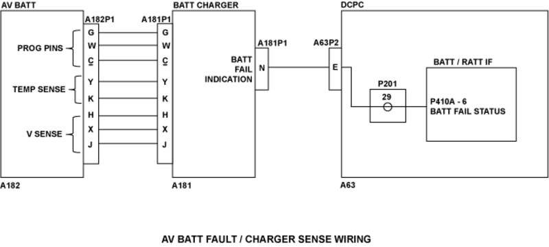
| Wiring Diagram: | 24-32-01 [ Global Express ] [ G5000 ] [ Global XRS ] |
Fault Description:
Fault message posted if DCPC BATT/RAT interface card receives the Avionic Battery Fail Status Discrete. Avionic Battery charger will send the Battery fail status if battery is too cold, too hot or if the charger detects a cell unbalance in the battery.
NOTE: If the avionics battery has been disconnected and then reconnected, an AV BATT FAIL message will be posted on the EICAS while on battery power only. The first time AC power (EXT AC or APU) is applied, the message will be removed.
Possible Causes:
- Avionics Battery (AV BATT) Charger
- AV BATT
- DC Power Center (DCPC) BATT/Ram-Air-Turbine (RAT) Interface Card
- DC Power Center (DCPC)
- Associated Wiring
Troubleshooting Tips:
Advisory Wire/Service Bulletin:
- AW700-24-0547 - Avionics battery heater harness failures
Forum Articles/Infoservice/Newsletter: None
Quick Links:
| Removal of the Avionics Battery | AMM 24-32-01-000-801 [ Global Express ] [ G5000 ] [ Global XRS ] |
| Installation of the Avionics Battery | AMM 24-32-01-400-801 [ Global Express ] [ G5000 ] [ Global XRS ] |
| Removal of the Battery Chargers | AMM 24-32-05-000-801 [ Global Express ] [ G5000 ] [ Global XRS ] |
| Installation of the Battery Chargers | AMM 24-32-05-400-801 [ Global Express ] [ G5000 ] [ Global XRS ] |
| Removal of the DC Power Center (DCPC) | AMM 24-61-00-000-801 [ Global Express ] [ G5000 ] [ Global XRS ] |
| Installation of the DC Power Center (DCPC) | AMM 24-61-00-400-801 [ Global Express ] [ G5000 ] [ Global XRS ] |
| Removal of the DC Power Center (DCPC) Battery/Ram-Air-Turbine Interface Unit | AMM 24-61-33-000-801 [ Global Express ] [ G5000 ] [ Global XRS ] |
| Installation of the DC Power Center (DCPC) Battery/Ram-Air-Turbine Interface Unit | AMM 24-61-33-400-801 [ Global Express ] [ G5000 ] [ Global XRS ] |
| Wire Repair | SPM 20-12-10 [ Global Express ] [ G5000 ] [ Global XRS ] |
Troubleshooting Recommendations:
- Make sure the Avionic Battery is not too hot or too cold. If it is not in a nominal operating temperature, take the necessary measures to return the Avionic Battery to a nominal operating temperature. Is the fault still present?
- If YES, continue with next step.
- If NO, do close out.
- Swap the AV BATT Charger with the APU BATT Charger and apply power to the A/C. Is the fault message still present?
- If YES, continue with next step.
- If NO, replace the defective Battery Charger.
- Disconnect the Avionic Battery connector A182P1. Disconnect the Avionic Battery Charger connector A181P1. Do a continuity check as follows:
NOTE: Make sure to inspect the condition of the Avionic Battery. Rectify if required.
From To Result A182P1-G Ground A182P1-W Ground A182P1-c Ground A182P1-Y Ground A182P1-K Ground A182P1-H Ground A182P1-X Ground A182P1-J Ground - If there is continuity, repair defective wiring as required.
- If there is no continuity, continue with next step.
- Do a continuity check as follows:
From To Result A182P1-G A181P1-G A182P1-W A181P1-W A182P1-c A181P1-c A182P1-Y A181P1-Y A182P1-K A181P1-K A182P1-H A181P1-H A182P1-X A181P1-X A182P1-J A181P1-J - If there is continuity, continue with next step.
- If there is no continuity, repair defective wiring as required.
- Access the DCPC logic assembly. Remove the BATT/RAT Interface card and do a continuity check as follows:
From To Result A181P1-N Ground - If there is continuity, repair defective aircraft wiring as required or replace the DCPC if defect is in the DCPC.
- If there is no continuity, continue with next step.
- Do a continuity check as follows:
From To Result A181P1-N P410A-6 - If there is continuity, continue with next step.
- If there is no continuity, repair defective aircraft wiring as required or replace DCPC if failure is in DCPC.
- Replace the BATT/RAT Interface Card in the DCPC. Is the fault still present?
- If YES, continue with next step.
- If NO, do close out.
- Replace the Avionic Battery.
- Do close out.