

04/26/24
Message Overview:
| DDG Reference: | 24-30-00 |
| Pilot Action (QRH): | ELEC 04-19 |
| System Description: | 24-00-00 |
| Schematic Diagram: | 24-70-00 [ Global Express ] [ G5000 ] [ Global XRS ] |
| Wiring Diagram: | 24-70-04 [ Global Express ] [ G5000 ] [ Global XRS ] |
Message Description:
A fault has been detected in the Electrical System.
Possible Causes:
- AC Power Center (ACPC) (A54)
- ACPC Microprocessor card
- ACPC Supervisor card
- Electrical Management System Control-and-Display Unit (EMS CDU) 1 (A94)
- Electrical Management System Control-and-Display Unit (EMS CDU) 2 (A91)
- Associated Wiring
Troubleshooting Tips:
Advisory Wire/Service Bulletin:
- AW700-24-0252 - "ELEC SYS FAULT" and or "ELEC SYS FAIL" - Nuisance CAS Message during Power Up
- AW700-24-0304 - "ELEC SYS FAIL" CAS message
Forum Articles/Infoservice/Newsletter: None
Flight Operation Notifications Manual (FONM):
- [ Global Express ] [ G5000 ] [ Global XRS ] FON 01-08 ELEC-001 - [ELEC SYS FAULT] (Advisory/Cyan) or [ELEC SYS FAIL] (Advisory/Amber) during Aircraft Power-Up
NOTES:
- If the ELEC SYS FAIL CAS message is active on Battery power only, the PMAT will not be accessible. For troubleshooting instructions refer to Observed Fault "247OBS007 - Electrical System Troubleshooting Via EMS CDU Signboard.
Quick Links:
| Removal of the AC Power Center (ACPC) | AMM 24-51-00-000-801 [ Global Express ] [ G5000 ] [ Global XRS ] |
| Installation of the AC Power Center (ACPC) | AMM 24-51-00-400-801 [ Global Express ] [ G5000 ] [ Global XRS ] |
| Removal of the AC Power Center (ACPC) Fault-Tolerant Supervisor | AMM 24-51-01-000-801 [ Global Express ] [ G5000 ] [ Global XRS ] |
| Installation of the AC Power Center (ACPC) Fault-Tolerant Supervisor | AMM 24-51-01-400-801 [ Global Express ] [ G5000 ] [ Global XRS ] |
| Removal of the AC Power Center (ACPC) Fault-Tolerant Microprocessor | AMM 24-51-05-000-801 [ Global Express ] [ G5000 ] [ Global XRS ] |
| Installation of the AC Power Center (ACPC) Fault-Tolerant Microprocessor | AMM 24-51-05-400-801 [ Global Express ] [ G5000 ] [ Global XRS ] |
| Removal of the Electrical Management System Control-and-Display Units (EMS CDU) | AMM 24-70-01-000-801 [ Global Express ] [ G5000 ] [ Global XRS ] |
| Installation of the Electrical Management System Control-and-Display Units (EMS CDU) | AMM 24-70-01-400-801 [ Global Express ] [ G5000 ] [ Global XRS ] |
| Access to Active Faults | AMM 45-45-00-970-802 [ Global Express ] [ G5000 ] [ Global XRS ] |
| Access to Stored Faults | AMM 45-45-00-970-803 [ Global Express ] [ G5000 ] [ Global XRS ] |
| Wire Repair - Maintenance Practices - ALL | SPM 20-12-10-02 [ Global Express ] [ G5000 ] [ Global XRS ] |
Troubleshooting Recommendations:
Select related CAIMS message below.
- Otherwise:
- If no CAIMS messages are present, continue with next step.
- If the ELEC SYS FAIL CAS message is active on Battery power only, the CAIMS will not be accessible. For troubleshooting instructions refer to Observed Fault "247OBS007 - Electrical System Troubleshooting Via EMS CDU Signboard".
- Access the EMS CDU signboard menu. Press on the SYSTEM button. Select COUNTERS. Are any of the counters indicating "0"?
- If the ACPC IN counter is 0, go to step 5.
- If YES, go to step 4.
- If NO, continue with next step.
- Access the COUNTERS on the opposite EMS CDU. Are any of the counters set to "0"?
- If the ACPC IN counter is 0, go to step 5.
- If YES, continue with next step.
- If NO, perform troubleshooting using task 247OBS007.
- Perform a wiring check between the EMS CDU and the affected component on that channel. Repair defective wiring as required.
- Remove the affected EMS CDU. Perform a resistance check of the databus channel between the affected EMS CDU and the ACPC as follows:
ACPC BUS 1 to EMS CDU 1.
From To Expected Result Result A94P1-5 A94P1-6 18Ω (± 2Ω) ACPC BUS 2 to EMS CDU 2
From To Expected Result Result A91P1-5 A91P1-6 18Ω (± 2Ω) - If resistance values are good, continue with next step.
- If resistance values are not good, troubleshoot the wiring interface.
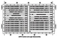
- Access the ACPC logic assembly. Swap the left microprocessor with the right microprocessor. Is the fault still present on the same side?
- If YES, continue with next step.
- If NO, replace defective microprocessor card.
- Swap the Left and right EMS CDUs. Is the fault still present on the same side?
- If YES, continue with next step.
- If NO, replace defective EMS CDU.
- Perform the ACPC card isolation procedure to identify is a card is faulty.
- If a card is faulty, replace card.
- If no card was found faulty, continue with next step.
- Replace the Supervisor card. Is the fault still present?
- If YES, replace the ACPC.
- If NO, do close out.
- Do close out.
