

08/06/24
Message Overview:
| DDG Reference: | None |
| Pilot Action (QRH): | ADVISORY 10-2 |
| System Description: | 30-21-00 |
| Schematic Diagram: | 30-21-00 [ Global Express ] [ G5000 ] [ Global XRS ] |
| Wiring Diagram: | 36-11-02 [ Global Express ] [ G5000 ] [ Global XRS ] |
Message Description:
Right Cowl Anti-Ice Valve has fault.
- The cowl anti-ice valve does not control the bleed air.
- The cowl anti-ice valve is failed closed with the engine stopped.
- The cowl anti-ice valve position indication is failed.
Possible Causes:
- Right Cowl Anti-Icing Valve (CAIV)
- Bleed Management Controller (BMC) (A69)
Troubleshooting Tips:
Advisory Wire/Service Bulletin:
- AW700-36-0365 - Bleed Monitoring Controller - Data Gathering to Reduce No Fault Found (NFF) rate
Forum Articles/Infoservice/Newsletter: None
Flight Operation Notifications Manual (FONM):
- [ Global Express ] [ G5000 ] [ Global XRS ] FON 01-16 ICE-001, [COWL A/ICE FAULT] (Advisory/Cyan) After Engine Shutdown.
NOTES:
- BMC NFF Action:
-To support the technical investigation, FSRs and Service Centers are requested to perform an NVM download and complete a condition report and (BMC) PN GG546-1017-XX questionnaire when troubleshooting or removing a Bleed Management Controller (BMC) PN GG546-1017-XX. - To avoid the display of any Bleed related CAS nuisance message after replacement of BMC due to internal failure, follow AW700-36-0365 instructions.
Quick Links:
| Removal of Bleed Management Controller (BMC) | AMM 36-11-33-000-801 [ Global Express ] [ G5000 ] [ Global XRS ] |
| Installation of Bleed Management Controller (BMC) | AMM 36-11-33-400-801 [ Global Express ] [ G5000 ] [ Global XRS ] |
| Removal of Cowl Anti-Icing Valve | AMM 30-21-01-000-801 [ Global Express ] [ G5000 ] [ Global XRS ] |
| Installation of Cowl Anti-Icing Valve | AMM 30-21-01-400-801 [ Global Express ] [ G5000 ] [ Global XRS ] |
| Access to Active Faults | AMM 45-45-00-970-802 [ Global Express ] [ G5000 ] [ Global XRS ] |
| Access to Stored Faults | AMM 45-45-00-970-803 [ Global Express ] [ G5000 ] [ Global XRS ] |
Troubleshooting Recommendations:
- Did the R COWL A/ICE FAULT cyan CAS message appear during or after engine shutdown?
- If YES, continue with next step.
- If NO, go to step 9.
- Ensure the engine has been shut down for at least 1 minute and the Cowl Anti-Ice Valve (CAIV) is selected OFF.
- Check the actual position of the CAIV by using the BLEED/AINTI-ICE synoptic page.
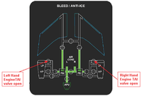
- Is the CAIV displayed as OPEN on the synoptic page?
- If YES, continue with next step.
- If NO, go to step 6.
- Is the R COWL A/ICE FAULT advisory CAS message still present?
- If YES, continue with next step.
- If NO, no further action is required. Do close out.
- Open the COWL doors and locate the CAIV.
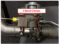
- Check the CAIV V-Band clamps position.
- If the V-Band clamps are installed 90° offset from each other, continue with next step.
- If the V-Band clamps are not installed 90° off-set from each other, re-orientate the V-Band clamps so that they are oriented 90° from each other.
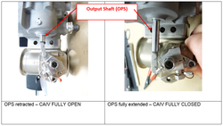
- Verify the valve butterfly position by observing the Output Shaft (OPS) position.
- If the OPS is retracted and the CAIV is displayed CLOSED on the Bleed Air/Anti-Ice synoptic page, go to step 10.
- If the OPS is fully extended, replace the CAIV and do close out.
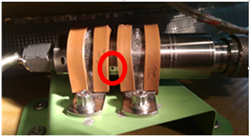
- Check the Pressure Transducer vent hole for installation clamp obstruction. Obstructing the Pressure Transducer vent hole will result in false pressure measurements and the display of CAI error messages.
- If the Pressure Transducer vent hole is covered by the installation clamps, rectify as required (see image below) and do close out.
- If the Pressure Transducer vent hole is not obstructed, continue with next step.
- Using the PMAT, access the Active Faults/Stored Faults as per AMM Tasks.
- Select related CAIMS message below:
- Do close out.


