

02/07/20
Message Overview:
Fault Message:
[ACSC2-A] RH FLOW CONT VLV CMD /FCV
Fault Code:
2163321ECS
Associated CAS:
| Reporting LRU: | Air Conditioning System Controller (ACSC) 2 |
| System Description: | 21-51-00 |
| Schematic Diagram: | 21-51-00 [ Global Express ] [ G5000 ] [ Global XRS ] |
| Wiring Diagram: | 21-51-02 [ Global Express ] [ G5000 ] [ Global XRS ] 21-52-02 [ Global Express ] [ G5000 ] [ Global XRS ] |
Fault Description:
The Right Flow Control Valve has been detected failed either in opened or closed position.
Possible Causes:
- Air Conditioning System Controller 2 (A88)
- Compressor Pneumatic Overheat-Sensors (CPNOH)
- Right Flow Control Valve (L30)
- Junction Box (JB6)
- Secondary-Power Distribution Assemblies (SPDA) 3 (A15)
- Data Acquisition Units (DAU) 2 (A18)
- Associated Wiring
Troubleshooting Tips:
Advisory Wire/Service Bulletin:
- AW700-21-0160 - "PACK FAULT" CAS message while CAIMS / OMS is active
Forum Articles/Infoservice/Newsletter: None
Quick Links:
| Removal of the Flow Control Valves | AMM 21-51-25-000-801 [ Global Express ] [ G5000 ] [ Global XRS ] |
| Installation of the Flow Control Valves | AMM 21-51-25-400-801 [ Global Express ] [ G5000 ] [ Global XRS ] |
| Removal of the Compressor Pneumatic Overheat-Sensors | AMM 21-52-17-000-801 [ Global Express ] [ G5000 ] [ Global XRS ] |
| Installation of the Compressor Pneumatic Overheat-Sensors | AMM 21-52-17-400-801 [ Global Express ] [ G5000 ] [ Global XRS ] |
| Removal of the Air-Conditioning System Controllers | AMM 21-60-21-000-801 [ Global Express ] [ G5000 ] [ Global XRS ] |
| Installation of the Air-Conditioning System Controllers | AMM 21-60-21-400-801 [ Global Express ] [ G5000 ] [ Global XRS ] |
| Removal of the Junction Box JB6 | AMM 24-00-13-000-801 [ Global Express ] [ G5000 ] [ Global XRS ] |
| Installation of the Junction Box JB6 | AMM 24-00-13-400-801 [ Global Express ] [ G5000 ] [ Global XRS ] |
| Removal of the Secondary-Power Distribution Assemblies | AMM 24-62-01-000-801 [ Global Express ] [ G5000 ] [ Global XRS ] |
| Installation of the Secondary-Power Distribution Assemblies | AMM 24-62-01-400-801 [ Global Express ] [ G5000 ] [ Global XRS ] |
| Removal of the Data Acquisition Units (DAU) | AMM 31-42-01-000-801 [ Global Express ] [ G5000 ] [ Global XRS ] |
| Installation of the Data Acquisition Units (DAU) | AMM 31-42-01-400-801 [ Global Express ] [ G5000 ] [ Global XRS ] |
| Wire Repair - Maintenance Practices - ALL | SPM 20-12-10 [ Global Express ] [ G5000 ] [ Global XRS ] |
Troubleshooting Recommendations:
- Gently tap on the right FCV. Did the valve move to the commanded position after tapping?
- If YES, replace the FCV.
- If NO, continue with next step.
NOTE: You may also verify that the FCV servo air line is properly secured into place. See image below.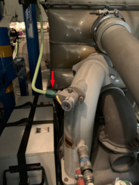
- Perform leak check of the sense line between FCV 2 and CPNOH.
- Swap FCV 2 with FCV 1.
- If the system check is good, replace TFCV 2 and do close out.
- If the fault remains, continue with next step.
- Swap CPNOH 2 with CPNOH 1.
- If the system check is good, replace CPNOH 2 and do close out.
- If the fault remains, continue with next step.
- Swap ACSC 2 with ACSC 1.
- If the system check is good, replace ACSC 2 and do close out.
- If the fault remains, continue with next step.
- Swap DAU 2 with DAU 1.
- If the system check is good, replace DAU 2 and do close out.
- If the fault remains, continue with next step.
- Swap SPDA 3 with SPDA 2.
- If the system check is good, replace SPDA 3 and do close out.
- If the fault remains, continue with next step.
NOTE 1: If SPDA 3 has been swapped with SPDA 4 a fault may have been transferred to another system on SPDA 2 ref Build 4 load lists with Pinout.xls.
NOTE 2: When swapping SPDA's, it is possible to loose your DC cabin feeds. Check the EMS-CDU Switch Control Page 3 under SYSTEM - CNTL button. First page is AC feeds 2nd and 3rd are DC feeds that will toggle off.
- Perform a wiring check of all wiring / circuits related to the FCV (Ref: Wiring Diagram: 21-52-00 Sheet 1 of 3, page 4).
- If wiring checks are not good, repair the defective associated wiring and do close out.
- If wiring checks are good, continue with next step.
- Remove JB6 and check K26 operation.
- Perform continuity check of JB6 (Ref: Wiring Diagram: 21-52-00 Sheet 2 of 3, page 4).
- If there is continuity, repair the defective associated wiring as required and do close out.
- if there is no continuity, continue with next step.
- Replace JB6.
- Do close out.
