10/09/20
Message Overview:
Fault Message:
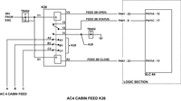
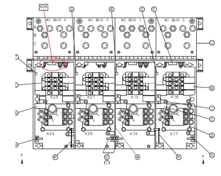
ACPC AC 4 CABIN FEED RELAY-K26
Fault Code:
2451363ACP
Associated CAS:
| Reporting LRU: | AC Power Center (ACPC) |
| System Description: | 24-50-00 |
| Schematic Diagram: | 24-51-00 [ Global Express ] [ G5000 ] [ Global XRS ] |
| Wiring Diagram: | 24-51-01 [ Global Express ] [ G5000 ] [ Global XRS ] |
Fault Description:
Secondary Logic Card 4 detects a discrepancy between the coil drive status and auxiliary contact status of the Contactor K26.
Possible Causes:
- AC Power Center (ACPC) Contactor (K26)
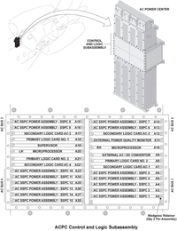
- Secondary Logic Card (SLC) 4
- Electronic Module 2 (EM2)
- AC Power Center (ACPC) (A54)
- AC Power Center (ACPC) TB402
- Associated Wiring
Troubleshooting Tips:
Advisory Wire/Service Bulletin: None
Forum Articles/Infoservice/Newsletter: None
If AC 4 CABIN FEED RELAY (K26) is tripped and is not resettable:
- Check K26 output (A2/B2/C2) and make sure all the three phases are not shorted to ground
Quick Links:
| Removal of the AC Power Center (ACPC) | AMM 24-51-00-000-801 [ Global Express ] [ G5000 ] [ Global XRS ] |
| Installation of the AC Power Center (ACPC) | AMM 24-51-00-400-801 [ Global Express ] [ G5000 ] [ Global XRS ] |
| Removal of the AC Power Center (ACPC) Secondary Logic | AMM 24-51-13-000-801 [ Global Express ] [ G5000 ] [ Global XRS ] |
| Installation of the AC Power Center (ACPC) Secondary Logic | AMM 24-51-13-400-801 [ Global Express ] [ G5000 ] [ Global XRS ] |
| Removal of the AC Power Center (ACPC) K-Series Relays (K16, K19, K23 and K26) | AMM 24-51-69-000-801 [ Global Express ] [ G5000 ] [ Global XRS ] |
| Installation of the AC Power Center (ACPC) K-Series Relays (K16, K19, K23 and K26) | AMM 24-51-69-400-801 [ Global Express ] [ G5000 ] [ Global XRS ] |
| Removal of the AC Power Center (ACPC) Electronic Modules | AMM 24-51-81-000-801 [ Global Express ] [ G5000 ] [ Global XRS ] |
| Installation of the AC Power Center (ACPC) Electronic Modules | AMM 24-51-81-400-801 [ Global Express ] [ G5000 ] [ Global XRS ] |
| Wire Repair - Maintenance Practices - ALL | SPM 20-12-10-02 [ Global Express ] [ G5000 ] [ Global XRS ] |
| AC Power Center Component Maintenance Manual | CMM 24-51-02 [ Global Express ] [ G5000 ] [ Global XRS ] |
Troubleshooting Recommendations:
- Swap SLC 4 with SLC 3.
- If system checks are good, replace SLC 4 and do close out.
- If fault remains, continue with next step.
- Perform a check for 28 VDC as follows:
From To Result K26-X1 Ground - If there is no voltage and there are no CAIMS fault messages related to EM2 fuses (F1, F2, F3 and F4), continue with next step.
- If there is no voltage and there is CAIMS fault messages related to EM 2 Fuses (F1, F2, F3 and F4), troubleshoot these messages first.
- If there is voltage, go to step 4.
- Check TB402-3 connection. Repair as required.
- If system checks are good, do close out.
- If fault remains, continue with next step.
- Remove aircraft power. Remove SLC 4 and disconnect K26-X1, K26-X2, K26-Y1, K26-Y2, K26-11 and K26-12. Perform a continuity check between the connections that follows:
From To Result K26-X2 (lug) Ground K26-Y2 (lug) Ground K26-12 (lug) Ground - If there is continuity, go to step 8.
- If there is no continuity, continue with next step
- Perform a continuity check as follows:
From To Result K26-11 (lug) Ground - If there is continuity, go to step 7.
- If there is no continuity, continue with next step.
- Check TB402-7 connection.
- If connection is correct, go to step 8.
- If connection is not correct, repair as required and do close out.
- Perform a continuity check between the connections that follows:
From To Result K26-Y2 (lug) SLC4-P411A-12 K26-X2 (lug) SLC4-P411A-13 K26-12 (lug) SLC4-P411C-17 - If there is continuity, replace K26 and do close out.
- If there is no continuity, continue with next step.
- Replace ACPC.
- Do close out.