10/09/20
Message Overview:
Fault Message:
ACPC ELECTRONIC MODULE #1-EM1 FAIL
Fault Code:
2451366ACP
Associated CAS:
| Reporting LRU: | AC Power Center (ACPC) |
| System Description: | 24-50-00 |
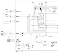
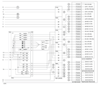
| Schematic Diagram: | 24-51-00 [ Global Express ] [ G5000 ] [ Global XRS ] |
| Wiring Diagram: | 24-51-01 [ Global Express ] [ G5000 ] [ Global XRS ] |
Fault Description:
The A/D Converter Card monitors fuses and Diodes status on Electronic Module (EM1).
- Voltage status on the output terminal for each fuse will be verified against related power input voltage in order to determine if any Fuse is open. If any open Fuse is found, the test for that Electronic Module will fail.
- Voltage status on the anode for each Diode will be compared against power input voltage. If an anode voltage is detected while no voltage is present at the associated power input, this will indicate a Diode short circuit fault and a Fuse open fault. The test of that Electronic Module will fail.
- The voltage status of Diode coil power will be compared against anode voltage on each Diode to determine if any Diode has failed open. This test will be limited to Diodes associated with power inputs.
Possible Causes:
- Electronic Module (EM1)
- A/D Converter Card
- Left Microprocessor Card
- AC Power Center (ACPC) (A54)
- Associated Wiring
Troubleshooting Tips:
Advisory Wire/Service Bulletin: None
Forum Articles/Infoservice/Newsletter: None
Quick Links:
| Removal of the AC Power Center (ACPC) | AMM 24-51-00-000-801 [ Global Express ] [ G5000 ] [ Global XRS ] |
| Installation of the AC Power Center (ACPC) | AMM 24-51-00-400-801 [ Global Express ] [ G5000 ] [ Global XRS ] |
| Removal of the AC Power Center (ACPC) Fault-Tolerant Microprocessor | AMM 24-51-05-000-801 [ Global Express ] [ G5000 ] [ Global XRS ] |
| Installation of the AC Power Center (ACPC) Fault-Tolerant Microprocessor | AMM 24-51-05-400-801 [ Global Express ] [ G5000 ] [ Global XRS ] |
| Removal of the AC Power Center (ACPC) External AC-to-DC Converter | AMM 24-51-17-000-801 [ Global Express ] [ G5000 ] [ Global XRS ] |
| Installation of the AC Power Center (ACPC) External AC-to-DC Converter | AMM 24-51-17-400-801 [ Global Express ] [ G5000 ] [ Global XRS ] |
| Removal of the AC Power Center (ACPC) Electronic Modules | AMM 24-51-81-000-801 [ Global Express ] [ G5000 ] [ Global XRS ] |
| Installation of the AC Power Center (ACPC) Electronic Modules | AMM 24-51-81-400-801 [ Global Express ] [ G5000 ] [ Global XRS ] |
| Wire Repair - Maintenance Practices - ALL | SPM 20-12-10-02 [ Global Express ] [ G5000 ] [ Global XRS ] |
| AC Power Center Component Maintenance Manual | CMM 24-51-02 [ Global Express ] [ G5000 ] [ Global XRS ] |
Troubleshooting Recommendations:
- Select EXT AC to on.
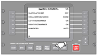
- On EMS CDU 1, select Diagnostic mode.
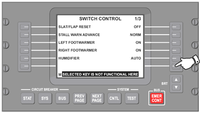
- Select SYSTEM - CNTL key (page 1/3).
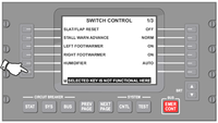
- Select lower left side key.
- Select lower right side key.
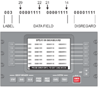
- On EMS CDU 1, select ACPC IN.
- Record labels 045 and 046.
Left Column Right Column Bit 29 28 27 26 25 24 23 22 21 20 19 18 17 16 15 14 Label 045 Label 046 - Refer to table below and compare data.
- Bit=0: voltage is not present.
- Bit=1: voltage is present.
Component Test Point 1 Test Point 2 Refer to step Input Voltage Label Bit Output Voltage Label Bit F1 ACPC A STA 045 14 D1 A STA 045 15 6 F2 ACPC B STA 045 17 D2 A STA 045 23 9 F3 ACPC C STA 045 27 D3 A STA 045 19 12 F4 EXT AC TRU 045 28 D4 A STA 045 26 15 F5 ACPC A STA 045 14 28 VDC 1-A 046 22 18 F6 ACPC B STA 045 17 28 VDC 2-A 046 23 22 F7 ACPC C STA 045 27 28 VDC 3-A 046 24 26 F8 EXT AC TRU 045 28 28 VDC 4-A 046 25 30 D1 D1 A STA 045 15 D1D4 C STA 045 18 34 D2 D2 A STA 045 23 D1D4 C STA 045 18 37 D3 D3 A STA 045 19 D1D4 C STA 045 18 40 D4 D4 A STA 045 26 D1D4 C STA 045 18 43 Table 1 Fuse F1 (Label 045 bit 14=1 and bit 15=0)
- Disconnect EM1 connector P407 and remove AD converter card. Perform continuity check as follows:
From To Result P407-1 Ground Fuse F2 (Label 045 bit 17=1 and bit 23=0).
- If there is no continuity, continue with next step.
- If there is continuity, go to step 18.
- Disconnect EM1 connector P407 and remove AD converter card. Perform continuity check as follows:
From To Result P407-2 Ground Fuse F3 (Label 045 bit 27=1 and bit 19=0)
- If there is no continuity, continue with next step.
- If there is continuity, go to step 18.
- Disconnect EM1 connector P407 and remove AD converter card. Perform continuity check as follows:
From To Result P407-3 Ground Fuse F4 (Label 045 bit 28 =1 and bit 26=0)
NOTE: If label 045 bit 28=0 and external AC is ON, investigate EXT AC TRU and EM3.- If there is no continuity, continue with next step.
- If there is continuity, go to step 18.
- Disconnect EM1 connector P407 and remove AD converter card. Perform continuity check as follows:
From To Result P407-4 Ground Fuse F5 (Label 045 bit 14=1 and label 046 bit 22=0).
- If there is no continuity, continue with next step.
- If there is continuity, go to step 18.
- Disconnect EM1 connector P407 and remove AD converter card and left microprocessor card. Perform continuity check as follows:
From To Result P407-15 Ground Fuse F6 (Label 045 bit 17=1 and label 046 bit 23=0).
- If there is no continuity, continue with next step.
- If there is continuity, go to step 18.
- Disconnect EM1 connector P407 and remove AD converter card and left microprocessor card. Perform continuity check as follows:
From To Result P407-16 Ground Fuse F7 (Label 045 bit 27=1 and label 046 bit 24=0).
- If there is no continuity, continue with next step.
- If there is continuity, go to step 18.
- Disconnect EM1 connector P407 and remove AD converter card and left microprocessor card. Perform continuity check as follows:
From To Result P407-17 Ground Fuse F8 (Label 045 bit 28=1 and label 046 bit 25=0).
- If there is no continuity, continue with next step.
- If there is continuity, go to step 18.
- Disconnect EM1 connector P407 and remove AD converter card and left microprocessor card. Perform continuity check as follows:
From To Result P407-18 Ground - If there is no continuity, continue with next step.
- If there is continuity, continue with next step.
Diode D1.
Troubleshooting tip and system description:
There are two conditions to get failure of diode D1.
Shorted diode D1: External AC power=ON.
Circuit breaker ACPC PWR A=OUT.
Label 045 bit 14=0
Label 045 bit 15=1
Label 045 bit 18=1
Opened diode D1: Battery master switch=ON
External AC power cord is not attached to the aircraft
Circuit breaker ACPC PWR A=IN
Label 045 bit 14=1
Label 045 bit 15=1
Label 045 bit 18=0
- Disconnect EM1 connector P407 and remove AD converter card. Perform continuity check as follows:
From To Result P407-1 Ground P407-9 Ground - If there is no continuity, continue with next step.
- If there is continuity, go to step 18.
Diode D2.
Troubleshooting tip and system description:
There are two conditions to get failure of diode D2.
Shorted diode D2: External AC power=ON.
Circuit breaker ACPC PWR B=OUT.
Label 045 bit 17=0
Label 045 bit 23=1
Label 045 bit 18=1
Opened diode D2: APU GEN power=ON
External AC power cord is not attached to the aircraft
Circuit breaker ACPC PWR A=OUT
Circuit breaker ACPC PWR B=IN
Circuit breaker ACPC PWR C=OUT
AC BUS 1 and AC BUS 2=unpowered
- Disconnect EM1 connector P407 and remove AD converter card. Perform continuity check as follows:
From To Result P407-2 Ground P407-9 Ground - If there is no continuity, continue with next step.
- If there is continuity, go to step 18.
Diode D3
Troubleshooting tip and system description:
There are two conditions to get failure of diode D3.
Shorted diode D3: External AC power=ON
Circuit breaker ACPC PWR C=OUT
Label 045 bit 27=0
Label 045 bit 19=1
Label 045 bit 18=1
Opened diode D3: APU GEN power=ON
External AC power cord is not attached to the aircraft
Circuit breaker ACPC PWR A=OUT
Circuit breaker ACPC PWR B=OUT
Circuit breaker ACPC PWR C=IN
Circuit breaker TRU 1=OUT
AC BUS 1 and AC BUS 2=unpowered
- Disconnect EM1 connector P407 and remove AD converter card. Perform continuity check as follows:
From To Result P407-3 Ground P407-9 Ground - If there is no continuity, continue with next step.
- If there is continuity, go to step 18.
Diode D4
Troubleshooting tip and system description:
There are two conditions to get failure of diode D4.
Shorted diode D4: Battery master switch=ON
Circuit breaker ACPC PWR A=IN
External AC power cord is not attached to the aircraft
Label 045 bit 28=0
Label 045 bit 26=1
Label 045 bit 18=1
Opened diode D4: Battery master switch=ON
External AC is ON
Circuit breaker ACPC PWR A=OUT
Circuit breaker ACPC PWR B=OUT
Circuit breaker ACPC PWR C=OUT
Label 045 bit 14=1
Label 045 bit 15=1
Label 045 bit 18=0
- Disconnect EM1 connector P407 and remove AD converter card. Perform continuity check as follows:
From To Result P407-4 Ground P407-9 Ground - If there is no continuity, continue with next step.
- If there is continuity, go to step 19.
- Replace EM1.
- If system checks are good, do close out.
- If fault remains, continue with next step.
- Replace ACPC.
- Do close out.