07/01/19
Message Overview:
Fault Message:
EMS CDU 2/ACPC RIGHT FTM-A10/WRG
Fault Code:
2470203CDU
Associated CAS:
| Reporting LRU: | Electrical Management System Control Display Unit (EMS CDU) 2 |
| System Description: | None |
| Schematic Diagram: | 24-51-00 [ Global Express ] [ G5000 ] [ Global XRS ] 24-70-00 [ Global Express ] [ G5000 ] [ Global XRS ] |
| Wiring Diagram: | 24-51-02 [ Global Express ] [ G5000 ] [ Global XRS ] 24-70-02 [ Global Express ] [ G5000 ] [ Global XRS ] 24-70-04 [ Global Express ] [ G5000 ] [ Global XRS ] |
Fault Description:
ARINC 429 communication between the AC Power Center (ACPC) and the Electrical Management System Control and Display Unit (EMS CDU) is faulty. The LRU transmits on periodic basis a test label that is turned around by the receiving LRU.
Possible Causes:
- Electrical Management System Control and Display Unit (EMS CDU) 2 (A91)
- AC Power Center (ACPC) (A54)
- AC Power Center (ACPC) Microprocessor Card
- AC Power Center (ACPC) Supervisor Card
- Junction Box (JB4)/PCB2
- Junction Box (JB4)
- AC Power Center (ACPC) Solid-State Power Controller (SSPC)
- AC Power Center (ACPC) Primary Logic Card (PLC) 1
- AC Power Center (ACPC) Primary Logic Card (PLC) 2
- AC Power Center (ACPC) Primary Logic Card (PLC) 3
- AC Power Center (ACPC) Secondary Logic Card (SLC) 1
- AC Power Center (ACPC) Secondary Logic Card (SLC) 2
- AC Power Center (ACPC) Secondary Logic Card (SLC) 3
- AC Power Center (ACPC) Secondary Logic Card (SLC) 4
- AC Power Center (ACPC) External Power Quality Monitor (EPQM)
- AC Power Center (ACPC) AC-to-DC Converter Card
- Associated Wiring
Troubleshooting Tips:
Advisory Wire/Service Bulletin: None
Forum Articles/Infoservice/Newsletter: None
- Make sure the Junction Box #4 is racked properly. Field experience revealed many cases of Junctions Boxes not installed properly.
- Flight deck effect:
- AC synoptic page is all magenta.
- DC synoptic page has magenta APU battery related info.
- On the EMS CDU, ACPC electrical loads are dashed.
- Alternative fault confirmation:
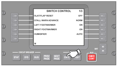
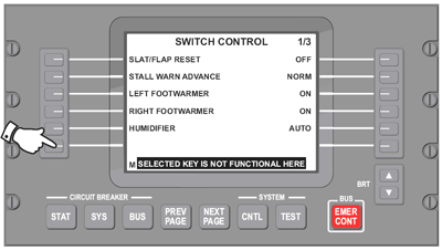
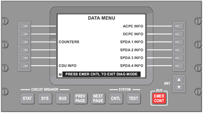
- On EMS CDU 2, select Diagnostic mode.
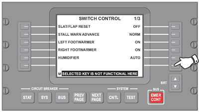
- Select SYSTEM - CNTL key (page 1/3).
- Select lower left side key.
- Select lower right side key.
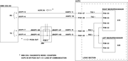
- On EMS CDU 2, select CIRCUIT BREAKER - SYS key and COUNTERS.
- ACPC IN= 0= loss of communication from ACPC right microprocessor to EMS CDU 2.
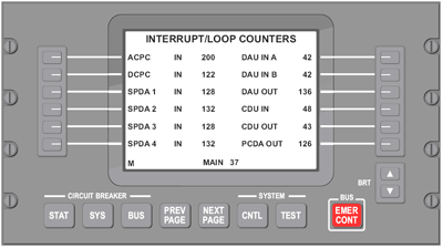
- ACPC IN= 0= loss of communication from ACPC right microprocessor to EMS CDU 2.
- On EMS CDU 2, select Diagnostic mode.
Quick Links:
| Removal of the Junction Box JB4 | AMM 24-00-05-000-801 [ Global Express ] [ G5000 ] [ Global XRS ] |
| Installation of the Junction Box JB4 | AMM 24-00-05-400-801 [ Global Express ] [ G5000 ] [ Global XRS ] |
| Removal of the Junction Box JB4 Circuit-Cards | AMM 24-00-06-000-801 [ Global Express ] [ G5000 ] [ Global XRS ] |
| Installation of the Junction Box JB4 Circuit-Cards | AMM 24-00-06-400-801 [ Global Express ] [ G5000 ] [ Global XRS ] |
| Removal of the AC Power Center (ACPC) | AMM 24-51-00-000-801 [ Global Express ] [ G5000 ] [ Global XRS ] |
| Installation of the AC Power Center (ACPC) | AMM 24-51-00-400-801 [ Global Express ] [ G5000 ] [ Global XRS ] |
| Removal of the AC Power Center (ACPC) Fault-Tolerant Supervisor | AMM 24-51-01-000-801 [ Global Express ] [ G5000 ] [ Global XRS ] |
| Installation of the AC Power Center (ACPC) Fault-Tolerant Supervisor | AMM 24-51-01-400-801 [ Global Express ] [ G5000 ] [ Global XRS ] |
| Removal of the AC Power Center (ACPC) Fault-Tolerant Microprocessor | AMM 24-51-05-000-801 [ Global Express ] [ G5000 ] [ Global XRS ] |
| Installation of the AC Power Center (ACPC) Fault-Tolerant Microprocessor | AMM 24-51-05-400-801 [ Global Express ] [ G5000 ] [ Global XRS ] |
| Removal of the AC Power Center (ACPC) Primary Logic | AMM 24-51-09-000-801 [ Global Express ] [ G5000 ] [ Global XRS ] |
| Installation of the AC Power Center (ACPC) Primary Logic | AMM 24-51-09-400-801 [ Global Express ] [ G5000 ] [ Global XRS ] |
| Removal of the AC Power Center (ACPC) Secondary Logic | AMM 24-51-13-000-801 [ Global Express ] [ G5000 ] [ Global XRS ] |
| Installation of the AC Power Center (ACPC) Secondary Logic | AMM 24-51-13-400-801 [ Global Express ] [ G5000 ] [ Global XRS ] |
| Removal of the AC Power Center (ACPC) External AC-to-DC Converter | AMM 24-51-17-000-801 [ Global Express ] [ G5000 ] [ Global XRS ] |
| Installation of the AC Power Center (ACPC) External AC-to-DC Converter | AMM 24-51-17-400-801 [ Global Express ] [ G5000 ] [ Global XRS ] |
| Removal of the AC Power Center (ACPC) AC External-Power Quality Monitor | AMM 24-51-21-000-801 [ Global Express ] [ G5000 ] [ Global XRS ] |
| Installation of the AC Power Center (ACPC) AC External-Power Quality Monitor | AMM 24-51-21-400-801 [ Global Express ] [ G5000 ] [ Global XRS ] |
| Removal of the AC Power Center (ACPC) Solid-State Power Controller | AMM 24-51-53-000-801 [ Global Express ] [ G5000 ] [ Global XRS ] |
| Installation of the AC Power Center (ACPC) Solid-State Power Controller | AMM 24-51-53-400-801 [ Global Express ] [ G5000 ] [ Global XRS ] |
| Removal of the Electrical Management System Control-and-Display Units (EMS CDU) | AMM 24-70-01-000-801 [ Global Express ] [ G5000 ] [ Global XRS ] |
| Installation of the Electrical Management System Control-and-Display Units (EMS CDU) | AMM 24-70-01-400-801 [ Global Express ] [ G5000 ] [ Global XRS ] |
| Wire Repair - Maintenance Practices - ALL | SPM 20-12-10-02 [ Global Express ] [ G5000 ] [ Global XRS ] |
Troubleshooting Recommendations:
- Swap EMS CDU 2 with EMS CDU 1.
- If system checks are good, replace EMS CUD 2 and do close out.
- If fault remains, continue with next step.
- Swap ACPC microprocessor cards.
- If system checks are good, replace defective ACPC microprocessor card and do close out.
- If fault remains, continue with next step.
- Replace ACPC supervisor card.
- If system checks are good, do close out.
- If fault remains, continue with next step.
- For EMI Filter/Wiring check
- Remove both microprocessor cards.
- Perform wiring checks between EMS CDU, JB4 and ACPC.
- If wiring checks are not good, repair defective wiring as required and do close out.
- If wiring checks are good, continue with next step.
- Perform wiring checks between ACPC connectors and microprocessors.
- If wiring checks are not good, repair defective wiring as required and do close out.
- If wiring checks are good, continue with next step.
CAUTION: To prevent damage to the ACPC motherboard connectors, ensure that the wire jumper pin outside diameter (OD)/socket inside diameter (ID) does not exceed 0.025 inch.
- Replace EMS CDU.
- If system checks good, do close out.
- If fault remains, continue with next step.
- Swap ACPCs.
- If system checks good, replace defective ACPC and do close out.
- If fault remains, continue with next step.
- Replace JB4.
- If system checks good, do close out.
- If fault remains, continue with next step.
- For ACPC Data Bus check
- Make sure that the EXT AC cord is not connected to the aircraft.
- Remove one of fifteen SSPC cards one at a time and set Battery Master Switch to ON to determine faulty SSPC.
NOTE: Monitor the fault via the AC Synoptic page or the Counters (EMS CDU Diagnostic Mode). - Replace defective SSPC.
- If system checks good, do close out.
- If fault remains, continue with next step.
- Remove one of three PLC cards one at a time and set Battery Master Switch to ON to determine faulty PLC.
- Replace defective PLC.
- If system checks good, do close out.
- If fault remains, continue with next step.
- Remove one of four SLC cards one at a time and set Battery Master Switch to ON to determine faulty SLC.
- Replace defective SLC.
- If system checks good, do close out.
- If fault remains, continue with next step.
- Replace EPQM.
- If system checks good, do close out.
- If fault remains, continue with next step.
- Replace A/D converter card.
- If system checks good, do close out.
- If fault remains, continue with next step.
- Replace ACPC.
- Do close out.
Detail Troubleshooting with pin assignment