12/11/19
Message Overview:
Fault Message:
LEFT COWL AI VALVE CMD /L CAIV
Fault Code:
3615315BMC
Associated CAS:
| Reporting LRU: | Bleed Management Controller (BMC) 1 |
| System Description: | 30-21-00 |
| Schematic Diagram: | 30-21-00 [ Global Express ] [ G5000 ] [ Global XRS ] |
| Wiring Diagram: | 36-11-01 [ Global Express ] [ G5000 ] [ Global XRS ] |
Fault Description:
The Left Cowl Anti-Ice Valve position reported to the Bleed Management Controller (BMC) does not agree with the L COWL ANTI-ICE switch position or does not regulate the pressure properly. Inhibited during take-off and Landing.
Possible Causes:
- Left Engine Cowl Anti-Ice Valve (CAIV)
- Left Engine Cowl Anti-Ice Valve (CAIV) Switch
- Bleed Air Control Panel (AP8)
- Anti-Ice Left Cowl Switch (S9)
- Cowl Anti-Ice Relay (K1)
- Cowl Anti-Ice Relay (K2)
- Ice Detector 1 (E48)
- Ice Detector 2 (E49)
- Left Engine Cowl Anti-Ice Pressure Transducer
- Left Engine In-line Pressure Regulator Valve
- Bleed Management Controller (BMC) 1 (A69)
- Associated Wiring
Troubleshooting Tips:
Advisory Wire/Service Bulletin:
- AW700-36-0365 - Bleed management controller - Data Gathering to Reduce No Fault Found (NFF) rate
Forum Articles/Infoservice/Newsletter:
NOTE: Make sure the BMC Questionnair is filled out and sent to Bombardier.
CAIV Position and Status Logic (used for synoptic page).
Quick Links:
| Removal of the Cowl Anti-Icing Valve | AMM 30-21-01-000-801 [ Global Express ] [ G5000 ] [ Global XRS ] |
| Installation of the Cowl Anti-Icing Valve | AMM 30-21-01-400-801 [ Global Express ] [ G5000 ] [ Global XRS ] |
| Removal of the Bleed Management Controller | AMM 36-11-33-000-801 [ Global Express ] [ G5000 ] [ Global XRS ] |
| Installation of the Bleed Management Controller | AMM 36-11-33-400-801 [ Global Express ] [ G5000 ] [ Global XRS ] |
| In-line Pressure Regulator Valve P/N 540-1394-2 | EIPC 30-21-05-01 [ Global Express ] [ G5000 ] [ Global XRS ] |
| Removal of the forward Anti-Ice Air Duct | EMM 30-21-05-000-801 [ Global Express ] [ G5000 ] [ Global XRS ] |
| Installation of the forward Anti-Ice Air Duct | EMM 30-21-05-400-801 [ Global Express ] [ G5000 ] [ Global XRS ] |
| Remove the Thermal Anti-Icing System | PPBU 71-00-02-504 [ Global Express ] [ G5000 ] [ Global XRS ] |
| Install the Thermal Anti-Icing System | PPBU 71-00-02-324 [ Global Express ] [ G5000 ] [ Global XRS ] |
| Wire Repair - Maintenance Practices - ALL | SPM 20-12-10-02 [ Global Express ] [ G5000 ] [ Global XRS ] |
Troubleshooting Recommendations:
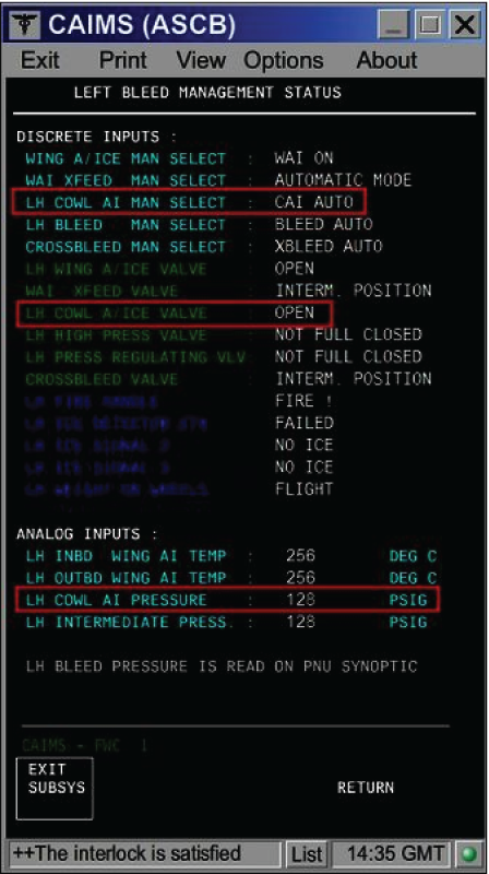
- On the PMAT, access CAIMS -> SYSTEM DIAG -> ATA 36 -> Select BMC 1 -> LRU TEST -> L BMC Discrete & analog input data. On the Bleed Air Control panel, set the L CAIV switch to all three positions consecutively while observing the CAIMS BMC data page.
- If the switch position displayed on the data page does not match with the actual switch position, go to step 17.
- When compared with the right side data page (BMC 2), if the LH COWL AI Pressure displayed on the data page is not correct, go to step 19.
- If the Cowl A/Ice Valve position displayed on the data page does not match the actual position of the CAIV, continue with next step.
NOTE: If engine is off, the CAIV has to be in the OPEN position, independent of switch position.
- Check if fault code 3615315BMC was set on ground.
- If NO, go to step 6.
- If YES, continue with next step.
- Ensure the engine has been shut down at least for 1 minute and the Cowl Anti-Ice Valve switch is selected OFF. Is the 'L COWL A/ICE FAULT' advisory CAS message still present?
- If NO, do close out.
- If YES, continue with next step.
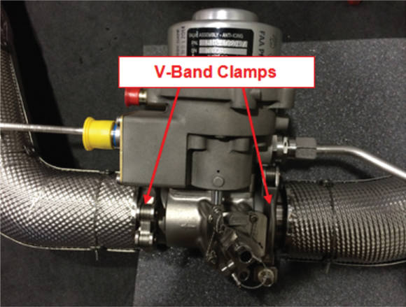
- Open the COWL doors and locate the CAIV. Check the CAIV V-Band clamps position.
- If the V-Band clamps are not installed 90 degrees off-set from each other, re-orientate the V-Band clamps so that they are oriented 90 degrees from each other and do close out.
- If the V-Band clamps are installed 90 degrees offset from each other, continue with next step.
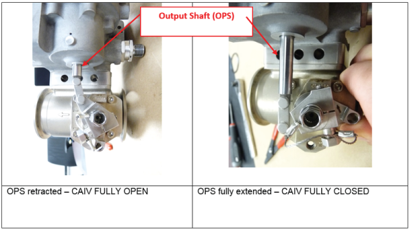
- Verify the valve butterfly position by observing the Output Shaft (OPS) position.
- If the OPS is retracted and the CAIV is displayed CLOSED on the Bleed Air/Anti-Ice synoptic page, go to step 7.
- If the OPS is fully extended, replace the CAIV and do close out.
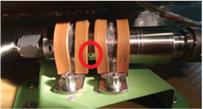
- Check the Pressure Transducer vent hole for installation clamp obstruction. Obstructing the Pressure Transducer vent hole will result in false pressure measurements and the display of CAI error messages.
- If the Pressure Transducer vent hole is covered by the installation clamps, rectify as required and do close out.
- If the Pressure Transducer vent hole is not obstructed, continue with next step.
- Swap CAIVs.
- If system checks are good, replace defective CAIV and do close out.
- If fault remains, continue with next step.
- Disconnect the left CAIV connector P720. On the Bleed Air control Panel, set the L CAIV switch to "ON". Make sure there is no voltage at P720-1.
- If there is no voltage, go to step 11.
- If there is voltage, continue with next step.
- Perform a wiring check between the CAIV and the Bleed Air Control Panel.
- If wiring checks are not good, repair defective wiring as required and do close out.
- If wiring checks are good, continue with next step.
- Replace the L CAIV switch.
- If system checks are good, do close out.
- If fault remains, continue with next step.
- On the Bleed Air control Panel, set the L CAIV switch to "OFF". Make sure there is 28 VDC at P720-1.
- If there is 28 VDC, go to step 13.
- If there is no voltage, continue with next step.
- Perform a wiring check between the CAIV and the Bleed Air Control Panel.
- If wiring checks are not good, repair defective wiring as required and do close out.
- If wiring checks are good, go to step 19.
- Disconnect CAIV connector P719 and P720. Disconnect BMC 1 connector A69P1. Perform a continuity check as follows:
From To Expected Result Result P719-3 Ground Open P719-4 Ground Continuity P719-5 Ground Continuity P720-2 Ground Continuity P720-3 Ground Continuity - If there is continuity, repair defective wiring as required and do close out.
- If there is no continuity, continue with next step.
- Perform a continuity check as follows:
From To Result P719-3 A69P1-13 - If there is no continuity, repair defective wiring as required and do close out.
- If there is continuity, continue with next step.
- Disconnect Bleed Air Control Panel connectors AP8P3 and AP8P4. Perform a continuity check as follows:
From To Result AP8P3-32 Ground AP8P4-32 Ground - If there is no continuity, go to step 18.
- If there is continuity on AP8P4-32, go to step 17.
- If there is continuity on AP8P3-32, continue with next step.
- Disconnect the Left Ice detector connector A48P1. Perform a continuity check as follows:
From To Result AP8P3-32 Ground - If there is continuity, repair defective wiring as required and do close out.
- If there is no continuity, replace the Left Ice Detector and continue with next step.
- Disconnect the Right Ice detector connector A49P1. Perform a continuity check as follows:
From To Result AP8P4-32 Ground - If there is continuity, repair defective wiring as required and do close out.
- If there is no continuity, replace the Right Ice Detector and continue with next step.
- Disconnect the Left Ice detector connector A48P1 and the Right Ice detector connector A49P1. Perform a continuity check as follows:
From To Result AP8P3-32 E48P1-6 AP8P4-32 E49P1-6 - If there is no continuity, repair defective wiring as required and do close out.
- If there is continuity, continue with next step.
- Perform a 28 VDC voltage check on AP8P3-31. Is 28 VDC present?
- If YES, go to step 21.
- If NO, continue with next step.
- Make sure the L COWL A/ICE VLV circuit breaker is set to "IN" and perform a wiring check between Bleed Air Control Panel and SPDA 2.
- If wiring checks are not good, repair defective wiring as required and do close out.
- If wiring checks are good, continue with next step.
- Perform a continuity check directly on the Bleed Air Control Panel as follows: L CAIV Switch position "ON":
From To Expected Result Result AP8J3-31 AP8J3-33 Open AP8J3-27 Panel Ground Continuity AP8J3-28 Panel Ground Open L CAIV Switch position "OFF":
From To Expected Result Result AP8J3-31 AP8J3-33 Continuity AP8J3-27 Panel Ground Open AP8J3-28 Panel Ground Continuity L CAIV Switch position "AUTO":
From To Expected Result Result AP8J3-31 AP8J3-33 Continuity AP8J3-31 Panel Ground Continuity AP8J3-27 Panel Ground Open AP8J3-28 Panel Ground Open - If the results are as per the table above, go to step 23.
- If the results are not as per the table above, continue with next step.
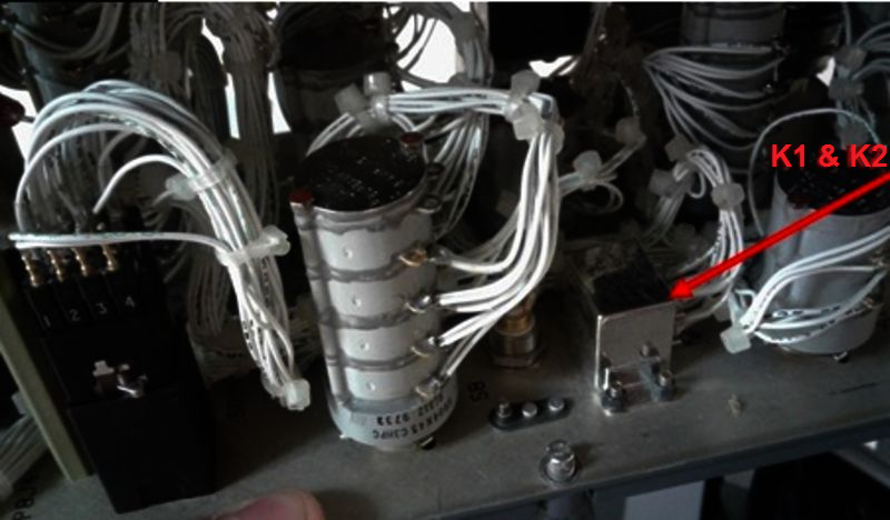
- Test the internal wiring of the panel, the L CAIV switch and the two relays (K1 and K2).
- If wiring checks are not good, repair defective wiring as required and do close out.
- If wiring checks are good, continue with next step.
- If defects are suspected with the K1 or K2 relays and perform a continuity check as follows: For K1:
From To Expected result Result X1 X2 Continuity A2 A3 Continuity C1 C2 Open D2 D3 Continuity For K2:
From To Expected result Result X1 X2 Continuity B2 B3 Continuity A1 A2 Open D2 D3 Continuity - If the test results are as expected, please note that it is possible a contact is "tack welded" in the de-energized position. If it is the case, only a test performed with power can reveal the defect.
- If results are not as in the tables above, continue with next step.
- Replace defective relay(s).
- If system checks are good, do close out.
- If fault remains, continue with next step.
- Swap the left Cowl Anti-Ice Pressure transducer and right Cowl Anti-Ice Pressure transducer.
- If system checks are good, replace left Cowl Anti-Ice Pressure transducer and do close out.
- If fault remains, continue with next step.
- Disconnect CAI Pressure transducer connector P718. Using a voltmeter, make sure there is 28 V at P718-1.
- If there is 28 VDC, go to step 28.
- If there is no voltage, check to make sure L BMC SENSORS circuit breaker is "IN" and continue with next step.
- Perform wiring checks between the Pressure sensor and SPDA 4.
- If wiring checks are not good, repair defective wiring as required and do close out.
- If wiring checks are good, continue with next step.
- Disconnect BMC 1 connector A69P1. Perform a continuity check as follows:
From To Expected Result Result P718-4 Ground Continuity P718-5 Ground Continuity P718-2 Ground Open P718-3 Ground Open - If there is continuity, repair defective wiring as required and do close out.
- If there is no continuity, continue with next step.
- Perform a continuity check as follows:
From To Result P718-2 A69P1-1 P718-3 A69P1-6 - If there is no continuity, repair defective wiring as required and do close out.
- If there is continuity, continue with next step.
- Perform troubleshooting of 3615425BMC.
- If system checks are good, do close out.
- If fault remains, continue with next step.
- Swap BMC 1 with BMC 2. Is the fault still present?
- If NO, replace BMC 1 and do close out.
- If YES, continue with next step.
- Replace the in-line pressure regulator valve.
- Do close out.