09/30/19
Message Overview:
Fault Message:
R CH B LOW TENSION IGNITN[1] RNG MA
Fault Code:
7327417RBR
Associated CAS:
| Reporting LRU: | Ignition Unit 1 |
| System Description: | 74-00-00 |
| Schematic Diagram: | 74-00-00 [ Global Express ] [ G5000 ] [ Global XRS ] |
| Wiring Diagram: | 74-00-01 [ Global Express ] [ G5000 ] [ Global XRS ] |
Fault Description:
There is an open or short circuit in the low-tension circuit of Ignition System 1. The fault is found between the Engine Electronic Controller (EEC) and the Ignition Unit 1. The low-tension ignition circuits are continuously monitored by the Full-Authority Digital Engine-Controller (FADEC).
Possible Causes:
- Ignition Unit 1
- Right Engine Electronic Controller (EEC)
- Secondary Power Distribution Assembly (SPDA) 3 (A15)
- Associated Wiring
Troubleshooting Tips:
Advisory Wire/Service Bulletin: None
Forum Articles/Infoservice/Newsletter: None
Quick Links:
| Connect Electrical Power to the Aircraft | AMM 24-00-00-861-801 [ Global Express ] [ G5000 ] [ Global XRS ] |
| Remove the Electrical Power from the Aircraft | AMM 24-00-00-861-802 [ Global Express ] [ G5000 ] [ Global XRS ] |
| Opening of Non-Thermal Circuit Breakers | AMM 24-00-00-863-801 [ Global Express ] [ G5000 ] [ Global XRS ] |
| Closing of Non-Thermal Circuit Breakers | AMM 24-00-00-863-802 [ Global Express ] [ G5000 ] [ Global XRS ] |
| Electrical/Electronic Safety Precautions | AMM 24-00-00-910-801 [ Global Express ] [ G5000 ] [ Global XRS ] |
| Engine Safety Precautions | AMM 71-00-00-910-801 [ Global Express ] [ G5000 ] [ Global XRS ] |
| Opening of the Cowls | AMM 71-10-00-010-801 [ Global Express ] [ G5000 ] [ Global XRS ] |
| Closing of the Cowls | AMM 71-10-00-410-801 [ Global Express ] [ G5000 ] [ Global XRS ] |
| Deactivation of the Thrust Reverser (for Maintenance) | AMM 78-30-00-040-801 [ Global Express ] [ G5000 ] [ Global XRS ] |
| Activation of the Thrust Reverser (for Maintenance) | AMM 78-30-00-440-801 [ Global Express ] [ G5000 ] [ Global XRS ] |
| Connection of Electrical Connectors | EMM 70-50-01-910-801 [ Global Express ] [ G5000 ] [ Global XRS ] |
| Removal of the Engine Electronic Controller (EEC) | EMM 73-21-01-000-801 [ Global Express ] [ G5000 ] [ Global XRS ] |
| Installation of the Engine Electronic Controller (EEC) | EMM 73-21-01-400-801 [ Global Express ] [ G5000 ] [ Global XRS ] |
| Removal of the Ignition Units | EMM 74-10-01-000-801 [ Global Express ] [ G5000 ] [ Global XRS ] |
| Installation of the Ignition Units | EMM 74-10-01-400-801 [ Global Express ] [ G5000 ] [ Global XRS ] |
| Safety Precautions - Maintenance Practices - ALL | SPM 20-00-01-02 [ Global Express ] [ G5000 ] [ Global XRS ] |
| Wire Repair - Maintenance Practices - ALL | SPM 20-12-10-02 [ Global Express ] [ G5000 ] [ Global XRS ] |
Troubleshooting Recommendations:
WARNING: Before touching the ignition system components, make sure of the conditions that follow:
- Isolate the power supply (make sure the applicable circuit breakers are open)
- After the power supply is isolated, do not touch the ignition system components before a minimum of three minutesThis must be done to make sure that the residual current decreases to a safe level. The ignition system has very high voltages which can kill.
- Perform a visual inspection of the ignition circuit wiring. Inspect for damage and proper installation.
NOTE: Look specially for signs of damage adjacent to clip locations.- If damage or defect is found, rectify or repair as required and do close out.
- If no damage or defect is found, continue with next step.
- Check if the CAS message R FADEC FAIL is displayed.
- If the CAS message R FADEC FAIL is displayed, troubleshoot the message first and continue with next step.
- If the CAS message R FADEC FAIL is not displayed, continue with next step.
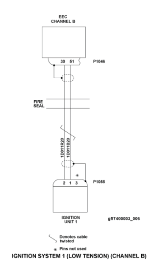
- Disconnect the EEC connector (P1046) and the ignition unit 1 connector (P1055). Perform a visual inspection of the associated wiring and EEC connector (P1046) and ignition unit 1 connector (P1055).
NOTE: Look specially for signs of chafing adjacent to clip locations, condition of connector pins and wiring kink or strain.- If defects are found, repair or rectify defects as required and do close out.
- If no defects are found, continue with next step.
- Perform a continuity check as follows:
From To Result P1055-2 P1046-30 P1055-1 P1046-51 - If there is no continuity, repair defective wiring as required and do close out.
- If there is continuity, continue with next step.
- Perform a insulation resistance check of the associated wiring between the EEC and the ignition unit 1 as follows:
From To Resistance Value Result P1046-30 Ground 20 ΜΩ or more P1046-51 Ground 20 ΜΩ or more - If the resistance value is less than the value specified in the table of if there is a short to ground, repair defective wiring as required and do close out.
- If there is no continuity or resistance value is as specified in the table, continue with next step.
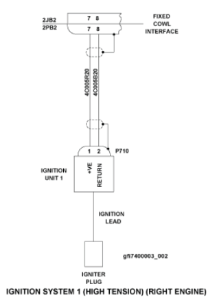
- Remove the fixed cowl interface connector (2PB2). Check if there is 28 VDC as follows:
From To Expected Result Result 2JB2-7 2JB2-8 28 VDC - If there is no 28 VDC, investigate the power source for SPDA 3 and do close out.
- If there is 28 VDC, continue with next step.
- Swap EEC 2 with EEC 1. Is the fault still present?
- If NO, replace EEC 2 and do close out.
- If YES, continue with next step.
- Replace Ignition Unit 1.
- Do close out.