10/07/19
Message Overview:
Fault Message:
L ENG [N1 SPEED PROBE]/WIRING
Fault Code:
7735316BRV
Associated CAS:
| Reporting LRU: | Engine Vibration-Monitoring Unit (EVMU) |
| System Description: | 77-30-00 |
| Schematic Diagram: | 77-31-00 [ Global Express ] [ G5000 ] [ Global XRS ] |
| Wiring Diagram: | 71-50-01 [ Global Express ] [ G5000 ] [ Global XRS ] 77-31-01 [ Global Express ] [ G5000 ] [ Global XRS ] |
Fault Description:
The fault message is set when there is a problem with the N1 speed input to the Engine Vibration-Monitoring Unit (EVMU).
Possible Causes:
- N1 Speed Probe
- Engine Vibration-Monitoring Unit (EVMU) (A42)
- Associated Wiring
Troubleshooting Tips:
Advisory Wire/Service Bulletin: None
Forum Articles/Infoservice/Newsletter: None
Quick Links:
| Engine Safety Precautions | AMM 71-00-00-910-801 [ Global Express ] [ G5000 ] [ Global XRS ] |
| Start the Engine | AMM 71-00-00-866-806 [ Global Express ] [ G5000 ] [ Global XRS ] |
| Engine Shutdown (Usual) | AMM 71-00-00-866-809 [ Global Express ] [ G5000 ] [ Global XRS ] |
| Removal of the Power Plant | AMM 71-00-00-000-801 [ Global Express ] [ G5000 ] [ Global XRS ] |
| Installation of the Power Plant | AMM 71-00-00-400-801 [ Global Express ] [ G5000 ] [ Global XRS ] |
| Opening of the Cowls | AMM 71-10-00-010-801 [ Global Express ] [ G5000 ] [ Global XRS ] |
| Closing of the Cowls | AMM 71-10-00-410-801 [ Global Express ] [ G5000 ] [ Global XRS ] |
| Removal of the Engine Vibration-Monitoring Unit (EVMU) | AMM 77-31-04-000-801 [ Global Express ] [ G5000 ] [ Global XRS ] |
| Installation of the Engine Vibration-Monitoring Unit (EVMU) | AMM 77-31-04-400-801 [ Global Express ] [ G5000 ] [ Global XRS ] |
| Thrust Reverser Safety Precautions | AMM 78-30-00-910-801 [ Global Express ] [ G5000 ] [ Global XRS ] |
| Deactivation of the Thrust Reverser (for Maintenance) | AMM 78-30-00-040-801 [ Global Express ] [ G5000 ] [ Global XRS ] |
| Activation of the Thrust Reverser (for Maintenance) | AMM 78-30-00-440-801 [ Global Express ] [ G5000 ] [ Global XRS ] |
| Wire Repair - Maintenance Practices - ALL | SPM 20-12-10-02 [ Global Express ] [ G5000 ] [ Global XRS ] |
Troubleshooting Recommendations:
CAUTION: DO NOT DO ELECTRICAL CHECKS INTO THE ENGINE ELECTRONIC CONTROLLER (EEC). IF YOU DO NOT OBEY THIS INSTRUCTION, DAMAGE TO THE EEC CAN OCCUR.
- Remove the electrical power from the aircraft.
- In the flight compartment, on the EMS CDU, open the circuit breakers that follow:
System Name Circuit Breaker Name Bus Name ENGINE L FADEC CH A BATT ENGINE L FADEC CH B BATT ENGINE L ENG IGN 1 BATT ENGINE L ENG IGN 2 BATT ENGINE L ENG FUEL HPSOV BATT ENGINE L ENG START A BATT ENGINE L ENG START B BATT THRUST REV L T/R CTL VALVE BATT THRUST REV L T/R LOWER LOCK BATT THRUST REV L T/R UPPER LOCK BATT - Perform a deactivation of the thrust reverser and open the cowls.
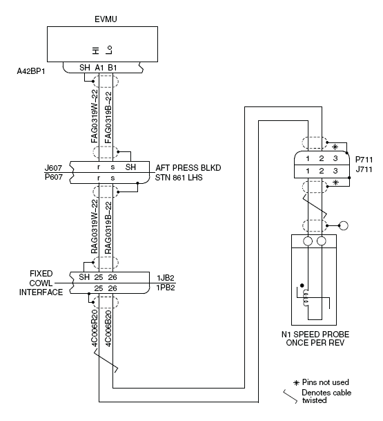
- Perform a visual inspection of the interface wiring, terminals and connectors for damage between EVMU (A42BP1) and N1 speed probes (P711).
NOTE: Look specially for signs of damage adjacent to clip locations, condition of connector pins and wiring that is kinked or strained.- If any damage found, repair or replace as required and go to step 16.
- If no damage and the fault message was stored in the Fault Confirmation above, then the fault could be intermittent and continue with next step.
- Monitor the system to see if the fault message occurs again.
- If the fault message is not active, go to step 16.
- If the fault message is active, continue with next step.
- Perform wiring checks between N1 Speed Probe (P711) and Fixed Cowl Interface (1PB2).
- If wiring checks are not good, repair defective wiring as required and go to step 16.
- If wiring checks are good, continue with next step.
- Perform wiring checks between F ixed Cowl Interface (1JB2) and A ft Pressure Bulkhead STN 861 LHS (P607).
- If wiring checks are not good, repair defective wiring as required and go to step 16.
- If wiring checks are good, continue with next step.
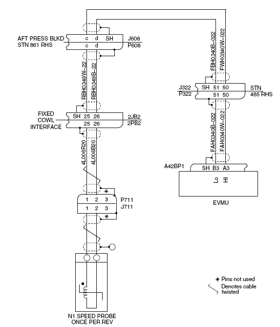
- Perform wiring checks between Fixed Cowl Interface (2JB2) and A ft Pressure Bulkhead STN 861 RHS (P608).
- If wiring checks are not good, repair defective wiring as required and go to step 16.
- If wiring checks are good, continue with next step.
- Perform wiring checks between Aft Pressure Bulkhead STN 861 LHS (J607) and EVMU (A42BP1).
- If wiring checks are not good, repair defective wiring as required and go to step 16.
- If wiring checks are good, continue with next step.
- Check for fault message L ENG [N1 SPEED PROBE]/WIRING.
- If the fault is not active, go to step 16.
- If the fault stays active, continue with next step.
- Perform a check for the insulation resistance of the interface between the connectors N1 Speed Probe to Fixed Cowl Interface.
From To Expected Result Result P711-1 Ground >20 megaohms P711-2 Ground >20 megaohms - If the resistance value is out of limit, repair defective wiring as required and go to step 16.
- If the resistance value is within limit, continue with next step.
- Perform a check for the insulation resistance of the interface between the connectors Fixed Cowl Interface to Aft Pressure Bulkhead.
From To Expected Result Result P607-r Ground >20 megaohms P607-s Ground >20 megaohms - If the resistance value is out of limit, repair defective wiring as required and go to step 16.
- If the resistance value is within limit, continue with next step.
- Perform a check for the insulation resistance of the interface between the connectors Aft Pressure Bulkhead to EVMU.
From To Expected Result Result A42BP1-A1 Ground >20 megaohms A42BP1-B1 Ground >20 megaohms - If the resistance value is out of limit, repair defective wiring as required and go to step 16.
- If the resistance value is within limit, continue with next step.
- Replace EVMU.
- If system checks are good, do close out.
- If fault remains, continue with next step.
- Replace the power plant.
- Close the cowls and activate the Thrust Reverser.
- Do close out.