06/22/21
Message Overview:
Message Name:
HF TUNING AND POOR RECEPTION
| Message Code: | 231OBS004 |
| Effectivity: | All |
| System: | HF Communication System |
| System Description: | 23-12-00 |
| Schematic Diagram: | 23-12-00 [ Global Express ] [ G5000 ] [ Global XRS ] |
| Wiring Diagram: | 23-12-01 [ Global Express ] [ G5000 ] [ Global XRS ] |
Message Description:
High Frequency (HF) 1 or 2 will not tune to a specific frequency or range of frequencies. No HF 1 or 2 internal or antenna faults reported by CAIMS.
Possible Causes:
None
Troubleshooting Tips:
Advisory Wire/Service Bulletin:
- Rockwell Collins SB MT-9042A-23-1 - COMMUNICATIONS - MT-9042A - TUNE FAULT MITIGATION REGARDING HIGH ANTENNA LOOP RESISTANCE
Forum Articles/Infoservice/Newsletter: None
NOTE 1: Make sure to carry out the resistance check as instructed in the 'Pretest' section 3.A.(1) (a) & (b) of SB MT-9042A-23-1 prior to performing the SB.
NOTE 2: Replacement of the HF Antenna Coupler is never required if due to low pressure. Checking the HF Antenna Coupler pressure is not a troubleshooting step in service. Neither required is the recharging the coupler pressure per AMM TASK 23-12-05-780-802. The HF Antenna Coupler is considered 'on-condition' and only requires replacement if the troubleshooting clearly identifies the coupler has a fault.
Quick Links:
| Removal of the HF Transceiver Mounting Tray | AMM 23-12-03-000-801 [ Global Express ] [ G5000 ] [ Global XRS ] |
| Installation of the HF Transceiver Mounting Tray | AMM 23-12-03-400-801 [ Global Express ] [ G5000 ] [ Global XRS ] |
| Functional Test (Pressure) of the High Frequency (HF) Communication Antenna Coupler | AMM 23-12-05-780-802 [ Global Express ] [ G5000 ] [ Global XRS ] |
| Removal of the HF Antenna Coupler Mounting Tray | AMM 23-12-07-000-802 [ Global Express ] [ G5000 ] [ Global XRS ] |
| Installation of the HF Antenna Coupler Mounting Tray | AMM 23-12-07-400-802 [ Global Express ] [ G5000 ] [ Global XRS ] |
Troubleshooting Recommendations:
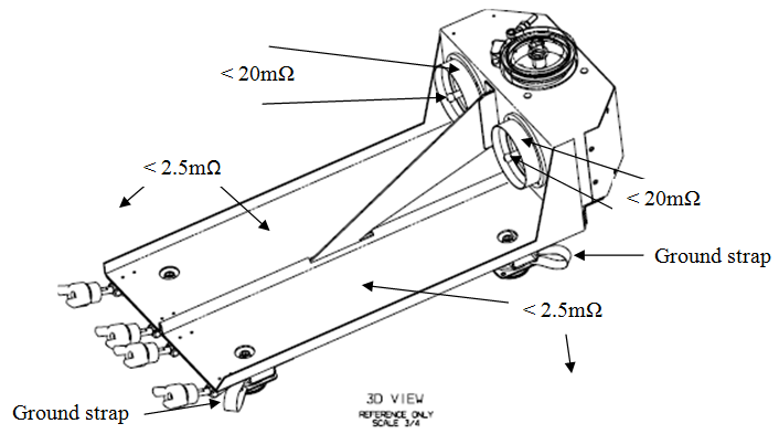
- Check bonding of coupler trays. Remove couplers from trays. Measure bonding from coupler center conductor to outer ring <20 mΩ as per Fig 1.
- If <20 mΩ, go to step 3.
- If >20 mΩ, continue with next step.
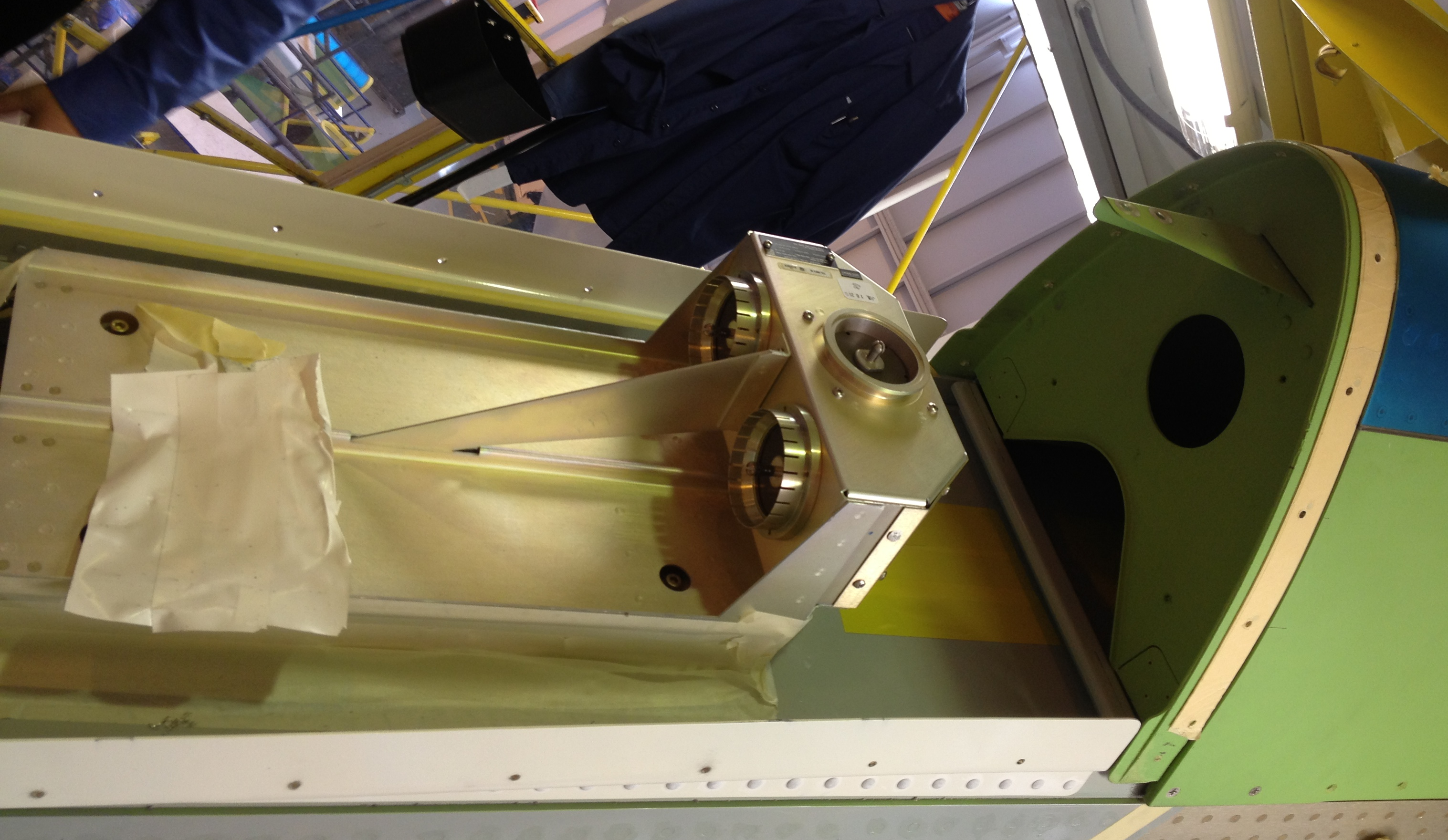
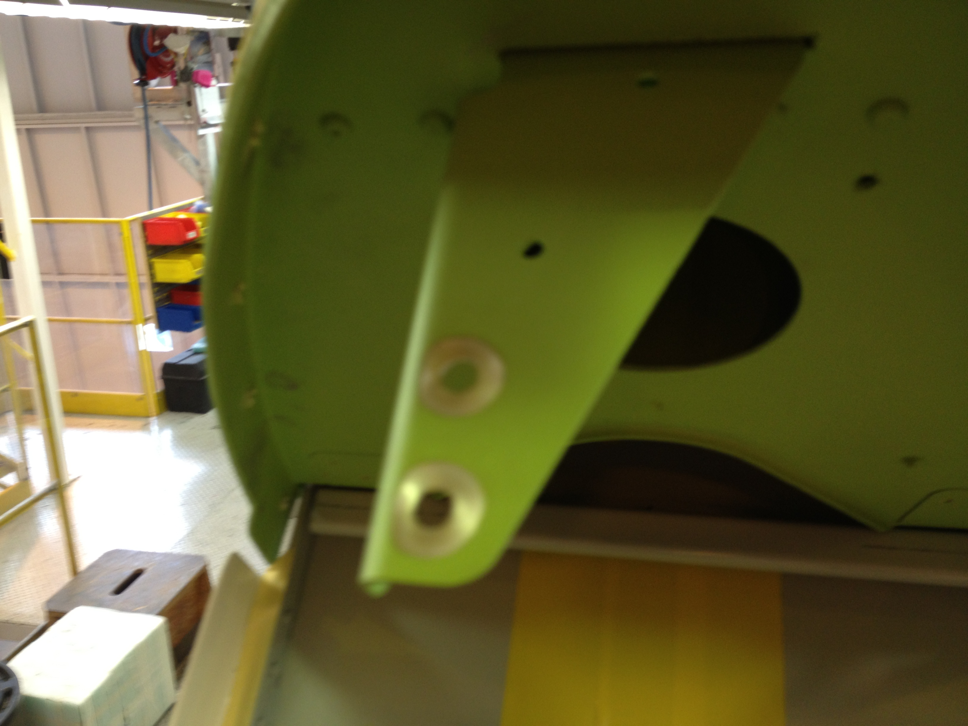
- Remove metallic strip linking coupler trays to antenna feed line as per Fig 2. Scrape off paint between screws anchor point as per Fig 3. Re-install metallic strip and apply humiseal over screws.
- Measure bonding from coupler trays to airframe <2.5 mΩ.
- If <2.5 mΩ, go to step 5.
- If >2.5 mΩ, continue with next step.
- Scrape off any paint to airframe at tray anchor points (x4). Verify coupler trays proper installation of ground straps (x4).
- Test HF as per maintenance manual.
- Do close out.