11/10/25
Message Overview:
Message Name:
ELECTRIC HYDRAULIC PUMPS STARTING CAUSING VARIOUS FAILURES
| Message Code: | 240OBS005 |
| Effectivity: | All |
| System: | Electrical Power |
| System Description: | 24-00-00 - Electrical Power |
| Schematic Diagram: | [Global Express] [ G5000 ] [ Global XRS ] 24-51-00-101 - Primary Power AC Power Distribution System [Global Express] [ G5000 ] [ Global XRS ] 24-61-00-101 - Primary Power DC Power Distribution System [Global Express] [ G5000 ] [ Global XRS ] 29-12-00-101 - Hydraulic System No. 1 and Mo. 2 [Global Express] [ G5000 ] [ Global XRS ] 29-13-00-101 - Hydraulic System No.3 |
| Wiring Diagram: | None |
Message Description:
Various systems, components or electric bus are noticed to fail momentarily when starting 1 or more Electric Hydraulic (HYD) Pump.
Possible Causes:
- AC Motor Pump 1B (B51)
- AC Motor Pump 2B (B52)
- AC Motor Pump 3A (B53)
- AC Motor Pump 3B (B54)
- AC Power Center (ACPC) (A54)
- Transformer Rectifier Unit 1 (A73)
- Transformer Rectifier Unit 2 (A74)
- Essential Transformer Rectifier Unit 1 (A75)
- Essential Transformer Rectifier Unit 2 (A76)
- AC Power Center (ACPC) Secondary Logic Card (SLC)
- Secondary Power Distribution Assembly (SPDA) 1 (A13)
- Secondary Power Distribution Assembly (SPDA) 2 (A14)
- Secondary Power Distribution Assembly (SPDA) 3 (A15)
- Secondary Power Distribution Assembly (SPDA) 4 (A16)
- DC Power Center (DCPC) (A63)
- Associated Wiring
Troubleshooting Tips:
Advisory Wire/Service Bulletin: None
Full Throttle Blog/Forum Articles/Infoservice/Newsletter: None
Flight Operation Notifications Manual (FONM): None
Quick Links:
| Standard Aircraft Configuration for Maintenance | [ G5000 ] [ Global Express ] [ Global XRS ] AMM12-00-00-867-801 |
| Connect Electrical Power to the Aircraft | [ G5000 ] [ Global Express ] [ Global XRS ] AMM24-00-00-861-801 |
| Electrical/Electronic Safety Precautions | [ G5000 ] [ Global Express ] [ Global XRS ] AMM24-00-00-910-801 |
| Electrostatic Discharge Safety Precautions | [ G5000 ] [ Global Express ] [ Global XRS ] AMM24-00-00-910-802 |
| Removal of the Transformer Rectifier Units | [ G5000 ] [ Global Express ] [ Global XRS ] AMM24-31-01-000-801 |
| Installation of the Transformer Rectifier Units | [ G5000 ] [ Global Express ] [ Global XRS ] AMM24-31-01-400-801 |
| Removal of the AC Power Center (ACPC) | [ G5000 ] [ Global Express ] [ Global XRS ] AMM24-51-00-000-801 |
| Installation of the AC Power Center (ACPC) | [ G5000 ] [ Global Express ] [ Global XRS ] AMM24-51-00-400-801 |
| Removal of the AC Power Center (ACPC) L-Series Contactors | [ G5000 ] [ Global Express ] [ Global XRS ] AMM24-51-33-000-801 |
| Installation of the AC Power Center (ACPC) L-Series Contactors | [ G5000 ] [ Global Express ] [ Global XRS ] AMM24-51-33-400-801 |
| Removal of the Secondary-Power Distribution Assemblies | [ G5000 ] [ Global Express ] [ Global XRS ] AMM24-62-01-000-801 |
| Installation of the Secondary-Power Distribution Assemblies | [ G5000 ] [ Global Express ] [ Global XRS ] AMM24-62-01-400-801 |
| Removal of the No. 1 and No. 2 Hydraulic-System AC-Motor-Driven Pumps | [ G5000 ] [ Global Express ] [ Global XRS ] AMM29-12-05-000-801 |
| Installation of the No. 1 and No. 2 Hydraulic-System AC-Motor-Driven Pumps | [ G5000 ] [ Global Express ] [ Global XRS ] AMM29-12-05-400-801 |
| Installation of the No. 3 Hydraulic-System AC-Motor-Driven Pumps | [ G5000 ] [ Global Express ] [ Global XRS ] AMM29-13-01-400-801 |
| Operational Test of the No. 3 Hydraulic-System AC-Motor-Driven Pumps | [ G5000 ] [ Global Express ] [ Global XRS ] AMM29-13-01-710-801 |
Troubleshooting Recommendations:
- Can the failure be attributed to always the same electric HYD pump (1B, 2B, 3A, or 3B) or does the failure occur when any of the HYD pumps is activated?
- If the failure can occur with any of the electric HYD pumps, go to step 8.
- If the failure is associated to only one electric HYD pumps, continue with next step.
- Access CAIMS System Diagnostics. Select ATA 24, AC Power Center A (B). Select Hydraulic Pump System Data and navigate to the page containing the hydraulic pump that is associated with the failure.
- Activate the HYD pump and inspect the Current for phase A, B and C. Is one of the phases different from the other two?
- If NO, go to step 6.
- If YES, continue with next step.
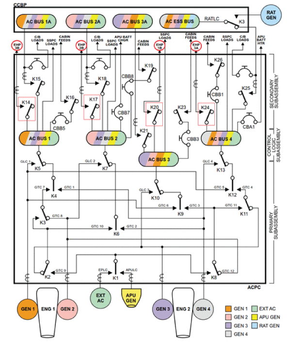
- Disconnect the electrical connector of the affected HYD pump and access the related contactor in the ACPC secondary subassembly. Perform a resistance check across the closed contacts (energized) of the related contactor. K20 for EHP 1B, K17 for EHP 2B, K24 for EHP 3A or K14 for EHP 3B. Is there a higher resistance on the suspected phase (A, B or C)?
- If YES, replace defective contactor and do close out.
- If NO, continue with next step.
- Interchange the affected EHP contactor with another EHP contactor. Is the fault still present?
- If NO, replace defective EHP contactor and do close out.
- If YES, continue with next step.
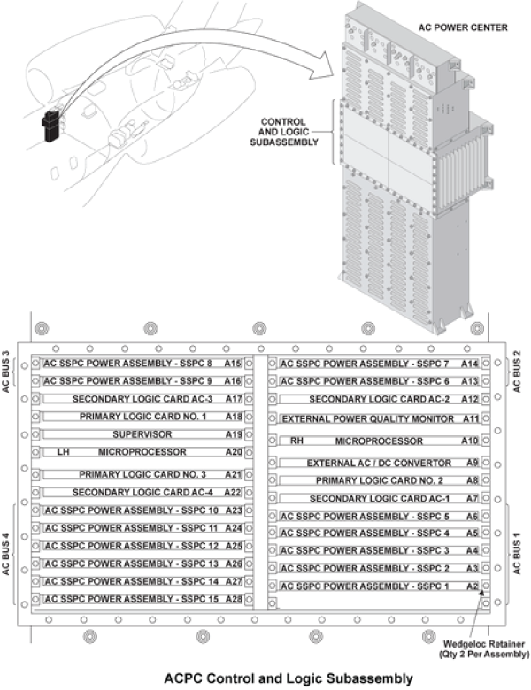
- Access the ACPC Logic subassembly. Interchange the Secondary Logic Card (SLC) associated with the suspected EHP.
- SLC 1 controls EHP 3B
- SLC 2 controls EHP 2B
- SLC 3 controls EHP 1B
- SLC 4 controls EHP 3A
- If the system checks are good, replace defective SLC and do close out.
- If the fault remains, continue with next step.
- Interchange the suspected EHP (1B and 2B can be swapped together and 3A and 3B can be swapped together).
- If system checks are good, replace defective EHP and do close out.
- If the fault remains, continue with next step.
- Is the failure associated to systems powered by only one SPDA?
- If the affected systems are powered by more than one SPDA, go to step 11.
- If the affected systems are powered by only one SPDA, continue with next step.
- Access the SPDA and inspect all connectors, making sure they are properly secured into place. Is the fault still present?
- If NO, do close out.
- If YES, continue with next step.
- Interchange the suspected SPDA with another SPDA. Is the fault still present?
- If NO, replace defective SPDA and do close out.
- If YES, continue with next step.
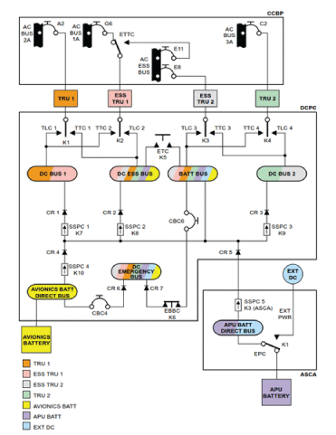
- On the Cockpit Circuit Breaker Panel (CCBP), set to OUT (pulled out) the Circuit Breaker (CB) for the TRUs, only one at a time. Every time a TRU is set to OUT, check if the failure still occurs. If the failure remains after a TRU CB is pulled, set it back to IN (pushed in) and set the next TRU to out. This has for effect to force the DCPC to reconfigure the Line and Transfer contactors so that the contactor associated to the TRU being set to OUT is isolated (see schematic below).
- If the failure is still present throughout the whole test and remains unaffected, repair or replace defective TRU and do close out.
- If the failure is no longer present when a specific contactor is isolated out, continue with next step.
- Interchange the TRU that was set to OUT with another TRU. Is the fault still present?
- If NO, replace defective TRU and do close out.
- If YES, continue with next step.
- Access and interchange the DCPC contactor associated to the TRU 1-K1 with ESS TRU 1-K2. Is the fault still present?
NOTE: Inspect the connection points inside the DCPC, make sure they are all tight and secure.
- If NO, replace TRU 1 contactor K1 and do close out.
- If YES, continue with next step.
- Access and interchange the DCPC contactor associated to the TRU 2-K4 with ESS TRU 2-K3. Is the fault still present?
- If NO, replace TRU 2 contactor K4 and do close out.
- If YES, continue with next step.
- You may need to troubleshoot the system or unit(s) affected by this issue. Make sure all defective wiring is checked for high resistance or short to ground.
- Do close out.