06/29/21
Message Overview:
Message Name:
ELECTRICAL INTERIOR CABIN DOOR RELEASE SWITCH INOPERATIVE
| Message Code: | 252OBS001 |
| Effectivity: | All |
| System: | Passenger Compartment |
| System Description: | 25-20-00 |
| Schematic Diagram: | 33-11-00 [ Global Express ] [ G5000 ] [ Global XRS ] |
| Wiring Diagram: | 33-11-05 [ Global Express ] [ G5000 ] [ Global XRS ] |
Message Description:
The Electrical Interior Cabin Door Release Switch does not function. Unable to close the Cabin Pocket Door.
Possible Causes:
- Cabin Door Switch Panel
- Door Release Switch Panel
- Door Electrical Latch Actuator
- Relay Drive Equipment (RDE) 1
- Relay Drive Equipment (RDE) 2
- Relay (K701)
- Relay (K702)
- DC Power Distribution Equipment (DCPDE) 1
- DC Power Distribution Equipment (DCPDE) 6
- Secondary Power Distribution Assembly (SPDA) 3 (A15)
- Electrical Management System Control-and-Display Unit (EMS CDU) 1 (A94)
- Electrical Management System Control-and-Display Unit (EMS CDU) 2 (A91)
- Pass Signs/Emer Lights Control Panel (AP13)
- Associated Wiring
Troubleshooting Tips:
Advisory Wire/Service Bulletin:
- AW700-44-0626 - VENUE Cabin Management System Intermittent Switch Panel Inoperative
Forum Articles/Infoservice/Newsletter:
- 2018-05-16 - ATA 25 Cabin door annunciation system description
Notice To Operators (NTO): None
Flight Operation Notifications Manual (FONM): None
NOTE: DOOR RELEASE switch power is controlled by the cockpit seat belt switch position. Make sure the switch is select to OFF while performing troubleshooting.
Quick Links:
| Removal of the Secondary-Power Distribution Assemblies | AMM 24-62-01-000-801 [ Global Express ] [ G5000 ] [ Global XRS ] |
| Installation of the Secondary-Power Distribution Assemblies | AMM 24-62-01-400-801 [ Global Express ] [ G5000 ] [ Global XRS ] |
| Removal of the Electrical Management System Control-and-Display Units (EMS CDU) |
AMM 24-70-01-000-801 [ Global Express ] [ G5000 ] [ Global XRS ] |
| Installation of the Electrical Management System Control-and-Display Units (EMS CDU) |
AMM 24-70-01-400-801 [ Global Express ] [ G5000 ] [ Global XRS ] |
| Removal of the PASS SIGNS/EMER LIGHTS Control Panel | AMM 33-51-13-000-801 [ Global Express ] [ G5000 ] [ Global XRS ] |
| Installation of the PASS SIGNS/EMER LIGHTS Control Panel | AMM 33-51-13-400-801 [ Global Express ] [ G5000 ] [ Global XRS ] |
| Wire Repair - Maintenance Practices - ALL | SPM 20-12-10-02 [ Global Express ] [ G5000 ] [ Global XRS ] |
Troubleshooting Recommendations:
- How many cabin pocket doors are inoperative?
- If all cabin doors are inoperative, go to step 16.
- If only one door is inoperative, continue with next step.
- Are both Door release switches inoperative at the same time (status light off)?
- If YES, go to step 6.
- If both door release switches status light is lit but the door is still not closing, go to step 18.
- If only one of the switches is inoperative, continue with next step.
- Disconnect the affected switch panel connector. Carry out a 28 VDC voltage check between pins 1 and 9 (see supplemental wiring diagram of Cabin door electric released latch).
- If voltage is good, replace the Door release switch panel and do close out.
- If voltage is not good, continue with next step.
- Using WD Cabin door electric released latch, check that all contacts are properly secured in the Terminal Module (TM).
- If contacts are not properly secured, rectify as required and do close out.
- If the contacts are properly secured into place, continue with next step.
- Perform wiring checks between the TM and switch panel.
- If wiring checks are good, replace the TM and do close out.
- If wiring checks are not good, repair defective wiring as required and do close out.
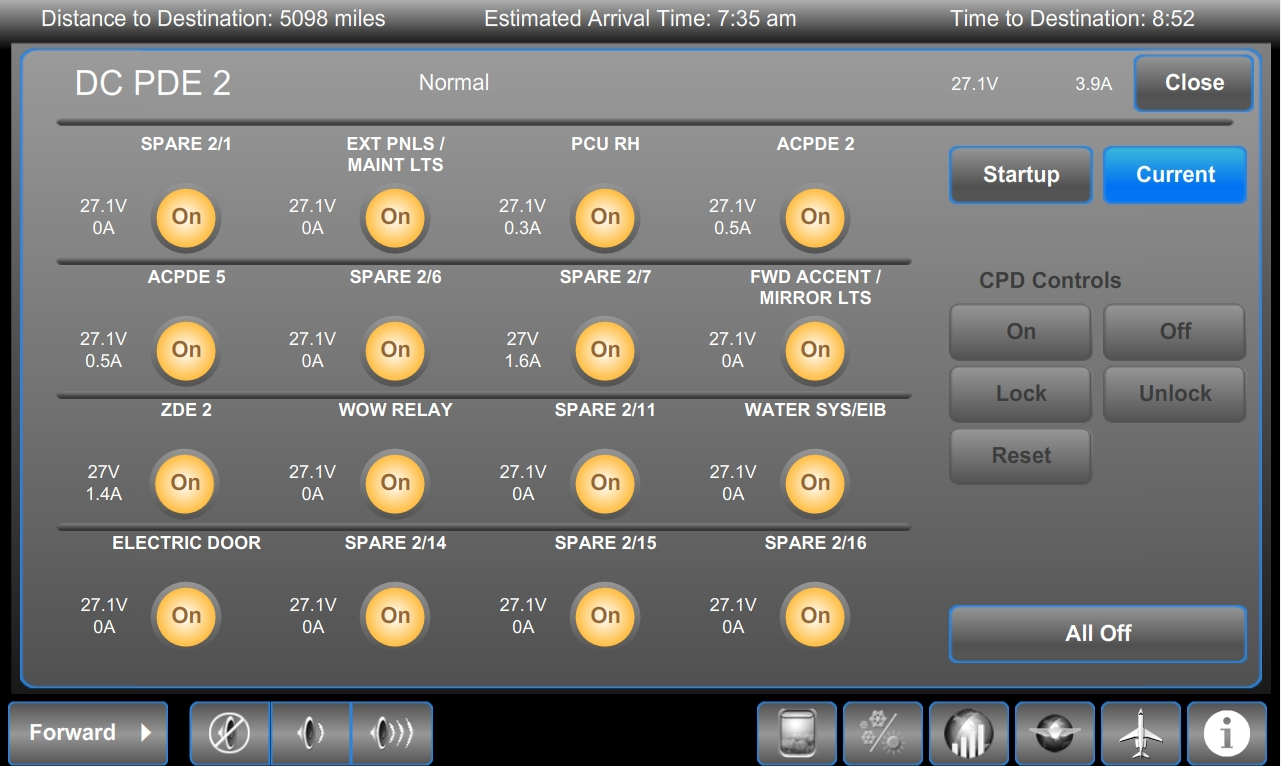
- Using the Galley Touchscreen Equipment (GTSE), confirm that the associated virtual Circuit Breaker (CB) is set to "ON".
- If the CB is not set to "ON", investigate why and set the CB to "ON" if possible and do close out.
- If the CB is set to "Locked", go to step 12.
- If the CB is set to "Trip" or "Blocked", go to step 13.
- If the CB shows an "X", go to step 8.
- If the CB is set to "ON", continue with next step.
- Make sure there is output voltage present at the DCPDE on the current system page.
- If output shows 28 VDC, go to step 9.
- If output shows 0 V, continue with next step.
- Swap the DCPDE with another DCPDE, leaving the TSM in place. Did the fault follow the DCPDE?
- If YES, replace defective DCPDE and do close out.
- If NO, replace TSM and do close out.
- Using WD Cabin door electric released latch, check that pin A2 of the relay has 28 VDC.
- If there is no 28 VDC, go to step 11.
- If there is 28 VDC at pin A2, continue with next step.
- Perform a wiring checks between pin A3 of the relay and pin 1 of the switch panel.
- If wiring checks are good, replace the relay and do close out.
- If wiring checks are not good, repair defective wiring as required and do close out.
- Perform wiring checks between pin A2 and associated DCPDE.
- If wiring checks are good, go to step 8.
- If wiring checks are not good, repair defective wiring as required and do close out.
- Set the CES maintenance switch to "ON" and unlock the CB. Set the CB to "ON" and do close out.
- Using WD Cabin door electric released latch, identify and disconnect the DCPDE output connector. Set the CES maintenance switch to "ON" and attempt to reset the CB.
- If the CB does not reset, go to step 8.
- If the CB resets, continue with next step.
- Perform a continuity check to ground at the DCPDE connector (aircraft side) to make sure the wiring is not shorted to ground.
- If there is continuity, repair defective wiring as required and do close out.
- If there is no continuity, continue with next step.
- Reconnect the DCPDE. Does the CB stay ON?
- If the CB trips again, go to step 8.
- If the CB stays ON, do close out.
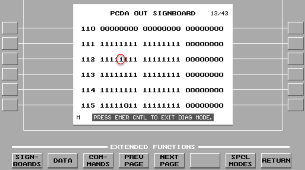
- Gain access the EMS CDU Signboard Menu. Select PCDA out, Labels 111 and 112. Verify that Built-In Test (BIT) 29 of Label 111 is not set to "0" (seat belt switch to AUTO) and that Built-In Test (BIT) 25 of Label 112 is not set to "0" (seat belt switch "ON").
- If one of the bits is set to "0" on only one EMS CDU, replace the defective EMS CDU and do close out.
- If one of the bits is set to "0" on both EMS CDU, continue with next step.
- Disconnect the Pass signs/Emer lights control panel.
- If Cabin Pocket door release operation is resumed, replace the Pass signs/Emer lights control panel and do close out.
- If Cabin Pocket door release operation is still inoperative, replace SPDA 3 and do close out.
- Verify that only one or both of the two switches is unable to activate the door release.
- If both of the switches do function, go to step 24.
- If only one of the two switches functions, continue with next step.
- Verify that there is a ground at the switch connector (aircraft side) and pin 8.
- If ground is not present, repair defective wiring as required and do close out.
- If ground is present, continue with next step.
- Swap the Door release switch with the one that functions.
- If system checks are good, replace defective Door release switch and do close out.
- If fault remains, continue with next step.
- Using WD Cabin door electric released latch, make sure that the ground wire contact is properly secured in the Terminal Module.
- If wire contact is not properly secured in the TM, rectify as required and do close out.
- If wire contact is properly secured in the TM, continue with next step.
- Perform a wiring check between the TM and the Door release switch.
- If wiring checks are not good, repair defective wiring as required and do close out.
- If wiring checks are good, continue with next step.
- Perform a wiring check between the switch connector and the associated RDE.
- If wiring checks are not good, repair defective wiring as required and do close out.
- If wiring checks are good, replace the TM and do close out.
- Perform a continuity check to ground at the associated RDE, connector P3 and pin 43.
- Is the ground is not present, repair defective wiring as required and do close out.
- If the ground is present, continue with next step.
- Swap RDE 1 with RDE 2. Is the fault still present?
- If NO, replace RDE 1 and do close out.
- If YES, continue with next step.
- Verify the integrity of the fuse on the electric latch actuator power feed line.
- If the fuse is burned, replace the fuse and do close out.
- If the fuse is good, continue with next step.
- Access the electric latch actuator. Carry out a 28 VDC voltage check at pin 1 and 3 of the actuator connector (aircraft side).
- If 28 VDC is not present, go to step 30.
- If 28 VDC is present, continue with next step.
- Perform a continuity check between the splice contacts A and B.
- If there is no continuity, replace the splice and do close out.
- If there is continuity, continue with next step.
- Perform a wiring check between pin 2 of the actuator connector (aircraft side) and the RDE connector P3-10.
- If there is continuity, replace the actuator and do close out.
- If there is no continuity, repair defective wiring as required and do close out.
- Perform a continuity check between the splice contacts C and D.
- If there is continuity, repair defective wiring between the TM and the actuator and do close out.
- If there is no continuity, continue with next step.
- Replace the splice.
- Do close out.