

05/06/21
Message Overview:
Message Description:
The RIGHT PYLON/WING LOOP is detected open circuit by IASC 1 during the system self-test. Check the loop and wiring continuity/resistance of the center conductor.

Possible Causes:
- R WAI/Pylon Loop Sensor 1A (MT54)
- R WAI/Pylon Loop Sensor 2A (MT56)
- R WAI/Pylon Loop Sensor 3A (MT58)
- R WAI/Pylon Loop Sensor 4A (MT60)
- R WAI/Pylon Loop Sensor 5A (MT42)
- R WAI/Pylon Loop Sensor 6A (MT118)
- Associated Wiring
Troubleshooting Tips:
Advisory Wire/Service Bulletin:
- AW300-36-0310 - Bleed Loop Connector Cleaning Tool
Forum Articles/Infoservice/Newsletter: None
Bleed Loop Routing and Visual Aid Guide
Troubleshooting Guide for Bleed Loops
NOTE: If the bleed loop resistance value is within limits try cleaning the bleed loop connections per SPM 51-25-00-110-801 and then reapply lubrication to the connections per SPM 20-20-00. Lubrication part number is called out in each bleed loop installation procedure. Run the aircraft after the cleaning and applying lubing procedure and see if the BLEED LOOP FAULT clears. You may use the BLEED LOOP CONNECTOR PIN CLEANING TOOL (36C-21-03).
Quick Links:
| Removal of the Right Aft-Fuselage Leak-Detection-Element | AMM 36-21-15-000-801 |
| Installation of the Right Aft-Fuselage Leak-Detection-Element | AMM 36-21-15-400-801 |
| Removal of the Right Cross-Under Duct Leak-Detection-Element | AMM 36-21-15-000-802 |
| Installation of the Right Cross-Under Duct Leak-Detection-Element | AMM 36-21-15-400-802 |
| Removal of the Right Center-Fuselage Leak-Detection-Element | AMM 36-21-15-000-803 |
| Installation of the Right Center-Fuselage Leak-Detection-Element | AMM 36-21-15-400-803 |
| Removal of the Wing-Root Leak-Detection Element | AMM 36-21-17-000-801 |
| Installation of the Wing-Root Leak-Detection Element | AMM 36-21-17-400-801 |
| Removal of the Wing-Middle Leak-Detection Element | AMM 36-21-17-000-802 |
| Installation of the Wing-Middle Leak-Detection Element | AMM 36-21-17-400-802 |
| Removal of the Wing-Outboard Leak-Detection Element | AMM 36-21-17-000-803 |
| Installation of the Wing-Outboard Leak-Detection Element | AMM 36-21-17-400-803 |
| Fenwal Safety Systems | CMM 26-14-47 |
| Solvent Cleaning | SPM 51-25-00-110-801 |
| Wiring - Maintenance Practices - ALL | SPM 20-12-00-02 |
| Wire Repair - Maintenance Practices - ALL | SPM 20-12-10-02 |
| Electrical Connectors - Maintenance Practice - ALL | SPM 20-20-00-02 |
Troubleshooting Recommendations:
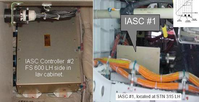
- Gain access to IASC 1 through the LH aft nose kidney panel 141BL.
- Disconnect connector A55P4 from the IASC and check resistance between pins 1 and 6. Resistance should be approximately 66.5 Ω.
- Isolate a system short through standard practices by isolating the six* different loops and wiring from the IASC. Repair faulty wire segment or replace loop as required.
*Only the first loop is identified, the IASC and MDC can not identify which section of a multiple loop segment is at fault during a short or open condition and will only list the first loop of the segment.
R Pylon and Wing Loop Information
R Pylon Bleed Loop Schematic and Information

NOTE: Measure Insulation resistance and line resistance of the detection loops as per the Leak Detection Elements Troubleshooting Sheet. Make sure line resistance & insulation values are within the specified limits.
NOTE: Often while troubleshooting this discrepancy the CAS is not usually present. However what you may find is higher than normal resistance such as 10 Ω or higher above nominal. It is not high enough to trip a bleed loop fault CAS message but high enough to assist in troubleshooting. When you get the resistance value down to nominal values then it is safe to say you've corrected the discrepancy.
NOTE: Dirty contacts can lead to an increase in the loop resistance values to the point of tripping a BLEED LOOP FAULT CAS/OPEN CIRCUIT B3 message. Make sure that all connectors of the applicable loop are clean. You may use the BLEED LOOP CONNECTOR PIN CLEANING TOOL (36C-21-03).