


05/06/16
Overview
The ATC transponder system is a remote-controlled transceiver system. It receives the interrogation pulses at 1,030 MHz and transmits the reply pulses at 1,090 MHz. The ATC transponder system replies to ground ATC radars and to airborne traffic alert and collision avoidance system (TCAS) interrogators.
The transponder modules are located in the Integrated Communication Units (ICUs) and provide Mode-A (Ident), Mode-C (Altitude) and Mode-S (Select) functions. The Mode-A response code is selected manually on the Radio Management Unit (RMU).
Each aircraft is assigned a unique mode-S address set by aircraft interconnect strapping. This mode-S code allows a ground station to interrogate a specific aircraft. It also allows the air-to-air interchanges required for TCAS collision avoidance.
ADS-B Out surveillance technology supports radar-like separation standards. The system brings significant safety and efficiency benefits, offering properly-equipped and certified aircraft more flexible, fuel-saving routes through airspace previously managed using only procedural air traffic control. Aircraft with ADS-B Out automatically transmit accurate position reports with integrity every second to Air Traffic Control (ATC). As a result, ADS-B Out will reduce separation minima for equipped aircraft and allow more aircraft to follow the most efficient flight trajectory. ADS-B Out operational capability is available via SB 700-34-062 for Global Express/XRS, or SB 700-1A11-34-036 for Global 5000.
Note:
The transponder is one of the three modules installed in the VHF communication (COM) units 1 and 2. The VHF COM unit is the line-replaceable unit (LRU).
The VHF COM units are installed in the main avionics compartment on Global Express/XRS and in the avionics rack on Global 5000. A clamp holds each unit in a mounting assembly. Each transponder connects to two ATC antennas. The ATC antennas are installed on the top and bottom of the fuselage.
The ATC transponder system connects to the TCAS through the ARINC 429 busses. The ATC transponder system also connects to the cluster module in the VHF COM unit through the radio communication bus (RCB). The cluster module supplies the interface between the RCB and the radio system bus (RSB). The ATC transponder system receives the remote radio commands from the radio management system through the RSB. (Although the cluster module also connects to the digital audio bus, it does not connect to the transponder; the transponder does not have an audio function.)
The ATC transponder system has a power-on self-test (POST) function that does a test of all of the system components. The POST starts after the system receives the pilot-activated self-test (PAST) command from the radio management system.
ATC Transponder System
The mode S diversity ATC transponder system is an automatic altitude and identification reporting unit that replies to ground ATC radars and to airborne TCAS interrogators. Mode S transponders enable the interrogators to interrogate a specific transponder by its mode S address.
Mode S transponders perform the same basic function as the traditional mode A/C transponder and provide the same data (and much more) to the ground stations and TCAS equipped aircraft. Mode S transponders enable the interrogators to interrogate a specific transponder by its mode S address. This results in only the target transponder replying instead of all transponders in the area responding. All mode S transponders have a unique 24-bit ICAO mode S ID address that is assigned by the governing regulatory agency. The mode S transponder ´squitter´ function transmits the mode S code without interrogation. When a TCAS system detects the squitter it will interrogate that transponder.
Mode S transponders reporting flight ID is commonly known as elementary surveillance. The Global serial numbers 9140 and above meet the elementary surveillance requirements and other Global serial numbers require SB 700-34-027 to comply. Flight ID refers to a flight plan call sign or aircraft registration marking.
Mode S Enhanced Surveillance (EHS) contains all the components of the Elementary Surveillance plus magnetic heading, indicated airspeed, mach number, vertical rate, roll angle, track angle rate, ground speed and selected altitude (including barometric pressure setting).
05/06/16
Transponder
The air traffic control transponder module is located in the integrated communication unit (ICU). It receives interrogations at 1,030 MHz and transmits replies at 1,090 MHz. The module operates with Mode S systems and air traffic control radar beacon systems (ATCRBS).
The transponder weighs 3.2 lbs (1.45 kg) and operates with a +28 VDC power supply. It supplies a maximum pulsed output power of 500 W (250 W minimum).
The transponder is a two-channel radar transceiver. It operates with the ATCRBS and the modes A, C, and S transponder systems.
- The ATCRBS is a ground station that uses a rotational antenna to transmit the interrogations to the aircraft. When the ATCRBS receives the reply, it uses the pulses' elapsed time to calculate the aircraft's distance (±500 feet). The angle at which the antenna receives the reply gives the aircraft's azimuth.
- The mode A reply contains the aircraft's identification code.
- The mode C reply contains the aircraft's barometric altitude data (±100 feet).
- The mode S reply contains the aircraft's identification code, barometric altitude data, and mode S address.
Note:
All aircraft have an identification code but only those aircraft with mode S transponders have a mode S address.
The transponder receives the barometric altitude data from the integrated avionics computer (IAC) through the RSB. The onboard wide area augmentation system (WAAS) that has the global navigation satellite sensor unit (GNSSU) function sends the position data. The transponder can supply this data as ARINC 429, ARINC 575, or RSB data outputs. The transponder includes the altitude data in its reply to the modes C or S interrogations.


Antennas
The ATC antenna is a blade-type, vertically-polarized antenna. The antenna has an N-type connector that connects to the transponder.
There are two omnidirectional antennas for each transponder, an upper antenna and a lower antenna. They are L-band blade antennas designed to operate in the 960 to 1,220-MHz frequency band and a maximum weight of 0.25 lbs (0.114 kg). The Mode S system uses both top-and bottom-mounted antennas in order to communicate with other aircraft at altitudes either above or below and with ground-based equipment sites.

RMU
Selecting the ATC window on the RMU allows ATC mode, code, and altitude reporting to be selected.

MADC
MADCs provide altitude information for ATC mode C operation.
08/06/18
System Operation
Transponder
The transponder supplies two special functions necessary for TCAS operation: mode S operation and antenna diversity.
- Mode S Operation - This function permits the transponder to transmit replies to all modes of interrogations. It also permits an interrogator to use an aircraft's mode S address to interrogate that one aircraft. (This type of discrete interrogation decreases the load on the radio frequency channels.)
- Antenna Diversity - This function permits the transponder to make an automatic selection of one of its two antennas. The transponder automatically connects to the antenna with the stronger interrogation signal. It subsequently uses this antenna to transmit the reply.
Mode S transponders operate much like mode A and mode C transponders and are fully compatible with ATCRBS radars. The most significant differences are:
- Mode S can transmit and receive more information per interrogation than ATCRBS transponder
- ATC is able to interrogate individual aircraft.
Mode S installations have a unique 24-bit electronic address. When an aircraft is fitted for a Mode S installation, this address is hardwired into the airframe by strapping of pins at the transponder connector. Any Mode S transponder subsequently installed on the aircraft will adopt this address.
Mode S transponders are designed to work in the ATCRBS environment, but they also can be addressed directly by mode S interrogations. The ATC ground station equipped for mode S operation transmits two types of interrogations, the mode S all call and the mode S discrete address interrogations.
Squitters
The squitters are transmitted by the transponder at a rate of once per second, without being interrogated. These "unsolicited replies" or squitters are used to provide TCAS II-equipped aircraft with the discrete address of the squittering aircraft, to enable the TCAS II system to acquire and track the aircraft using Mode S formats.
Elementary Surveillance
This concept takes basic surveillance a step further by adding the features of communications for data link and identification of the aircraft.
This basic functionality includes:
- 24-bit ICAO aircraft address
- Transponder capability report including selective interrogation (SI) code capability
- Altitude reporting
- Automatic reporting of aircraft identification (flight ID)
- Flight status (airborne/on the ground)
Flight ID
The flight ID is an eight-character identification that is entered from the RMU. The flight ID may contain the company-assigned number for that particular flight. If the company-assigned number is not available or not used, the flight ID then becomes the aircraft tail number. The flight ID supplements the unique 24-bit aircraft discrete address and is used by ATC for monitoring purposes.
Enhanced Surveillance
The enhanced surveillance uses the same concept of elementary surveillance with new added aircraft intent reporting fields.
These fields are:
- Selected vertical intent (vertical rate of descent)
- Track and turn report
- Heading
- Speed report (IAS)
The selected vertical intent report is used to indicate such items as the barometric altitude of the aircraft and the preselected altitude.
ADS-B Out Capability (Option)
ADS-B is a function for airborne or surface aircraft, or other surface vehicles operating within the airport surface movement area that periodically transmits its state vector (horizontal and vertical position, horizontal and vertical velocity) and other information. The source of the state vector is generated by onboard systems like the air data system, the IAC, and the GNSSU. ADS-B is automatic because no external stimulus is required. ADS-B is dependent because it relies on GPS and Transponder to provide surveillance information to other users. The aircraft originating the broadcast may or may not have knowledge of which users are receiving its broadcast. Any user within range may choose to receive and process the ADS-B surveillance information. ADS-B supports improved use of airspace, reduced ceiling/visibility restrictions, improved surface surveillance, and enhanced safety such as conflict management.
The 1090 MHz ADS-B system uses the Mode S Squitter to broadcast the aircraft/vehicle position, intent, and other relevant information over the RF medium.
The only action the pilot performs is to use the RMU to verify the system is on and monitor status (ADS-B FAIL or ADS-B DGR (Degraded)).
ATC Transponder Operation
The ATC transponder system control and indication is carried out by using the radio management units (RMUs).
ATC Code Select
The line select key opposite the ATC legend places the cursor over the transponder code to be changed. The large outer tuning knob controls the left two digits; the smaller inner knob controls the two right digits.
Since only one transponder can operate at a time, both RMUs will display the same transponder information. Therefore, if a code or mode is changed on one RMU, the other RMU will track it. Since the other RMU is being tuned by a remote source, the data changed will appear in yellow.
One transponder code may be stored in memory by pressing the STO button while the cursor is on the transponder code. To retrieve the code from the memory, press and hold the line select key for three seconds.
ATC Mode Select
The line select key associated with the transponder mode is also used to toggle between standby, transponder 1 ON, or transponder 2 ON.
Pressing the line select key associated with the transponder mode will place the cursor around the mode annunciator which then enables the tuning knobs to be used for mode selection. Either knob may be used to select a mode. The modes are described in the table below.
| MODE | FUNCTION |
|---|---|
| Standby | Receives interrogation signal but cannot reply |
| ATC ON | Replies on Modes S and A, no altitude reporting |
| ATC ALT | Replies on Modes A, C and S, with altitude reporting |
| TA ONLY | Replies on Modes A, C and S, with altitude reporting and TCAS traffic advisory mode (TA) is selected |
| TA/RA | Replies on Modes A, C and S, with altitude reporting and TCAS traffic advisory mode (TA) and resolution advisory mode (RA) are selected |

RMU – ATC/TCAS Control Page Menu
Pressing the PGE button provides access to the page menu. This menu allows access to the TCAS operational selections by using the ATC/TCAS select button.
ATC IDENT
Pressing the ID button places the transponder into ident mode for approximately 18 seconds, and an ID annunciator appears in the transponder window indicating that the transponder is in the identification mode.
Using the TUNE knobs adjusts the ATC flight ID. The ATC flight ID is not displayed unless FLIGHT ID - ENABLE is selected on both RMU setup pages (Ref 23-81-00).
Uncorrected altitude, including data, status, and source is displayed but cannot be modified. The TCAS controllable parameters are INTRUDER ALTITUDE (the adjacent line select key toggles between FL (flight level) and REL (relative) and TA DISPLAY (the adjacent line select key toggles between AUTO and MANUAL).
The active transponder selection is not annunciated on the ATC/TCAS control page. The ATC window on the radio tuning page shows the active transponder selection.

INTRUDER ALTITUDE
Using the adjacent line select key, the intruder altitude toggles between the following:
REL - The target altitude is displayed relative to one's own aircraft (e.g., +500, -1,200).
FL - The target altitude is displayed as a flight level (e.g.,FL200, FL100).
Note:
When the flight level is selected, the TCAS display returns to REL after 15 seconds.
TA DISPLAY
Using the adjacent line select key, the intruder TAdisplay toggles between the following:
AUTO - The traffic targets are displayed only when a TA or RA target condition exists.
MANUAL - All traffic targets are displayed in the viewing airspace.
Note:
For TCAS I installations, the TA display is removed and the RMU fixes the TA display to MANUAL.
ADS-B ON/OFF (Post SB700-34-062 (Global Express and XRS)/SB 700-1A11-34-036 (Global 5000))
Using the adjacent line select key, the ADS-B ON/OFF toggles between:
ON - The transponder is transmitting horizontal and vertical position and velocity to ATC.
OFF - The transponder is no longer transmitting position and velocity to ATC. Dashes "------------" display in the ADS-B status.
Note:
The transponder defaults the ADS-B ON/OFF status to ON at power on (cold start) and uses the last valid value on warm start.
Note:
The RMU ON/OFF discrete output is set to display a crew annunciator if the ADS-B functionality is turned OFF.
ADS-B STATUS
NORMAL - The ADS-B is operating normally.
DEGRADED - The ADS-B is operating in a degraded state or pressure altitude is invalid.
FAILED - The ADS-B Out transmissions have failed.
Indications
The ATC window displays the following annunciations:
- ATC Window Label
- ATC Mode
- ATC Reply Light
- ATC Ident
- ATC Status
- ATC Code
- ATC Test in Progress/Status

ATC Window Label
The ATC window label is on the upper corner of the window. It displays white ATC/TCAS.

ATC Mode
The ATC mode is under the ATC Code. It displays green STANDBY, ATC ON, ATC ALT, TA ONLY, TA/RA or TUNE ME.

ATC Reply Light
The ATC reply light is either an empty green box or a filled yellow box displayed to the right of the ATC window label.
- The empty green box indicates the transponder has no reply in progress
- The filled yellow box is displayed when the transponder is sending a reply

ATC Ident
A yellow ID annunciator is displayed to the immediate right of the ATC window label when the ID button is pressed.

ATC Status/Failure Warning
| MESSAGE | COLOR | STATUS |
|---|---|---|
| 'ADS-B OFF' CAS Message (Option) | Cyan | Setting the transponder to STANDBY will result in the cyan ADS-B OFF CAS message being displayed. |
|
'ATC MESSAGE' CAS Message |
Cyan | Post SB 700-1A11-34-027 (Global 5000) / 700-34-053 (Global Express/Global XRS): Incoming CPDLC messages will trigger the ATC MESSAGE advisory (cyan) CAS message and an aural tone. |
| ADS-B DGR (Option) | Yellow | ADS DGR will be displayed on the RMU in place of Flight ID if ADS-B Out is operating in a degraded state or pressure altitude from the ADCis invalid. On the ATC/TCAS RMU control page, ADS-B status will show DEGRADED in amber. Switching to the alternate transponder may clear the message. |
| ADS-B FAIL (Option) | Yellow | ADS-B Out function has failed or the onside GPS data is not available. Note: This annunciator displays during initial power-on until adequate GPS satellite data is attained,after which the message clears. |
| ATC ERR | Yellow | This annunciator is displayed when the transponder is signalling squitter fail. A PAST test should be initiated by a crew member. If the test fails, the transponder is not transmitting properly and the other side transponder must be selected. When the transponder passes the PAST, only the squitter function is not operating properly. |

ATC Code
The white four-digit ATC reply code is always present with leading zeroes if required. The reply code turns yellow when remotely tuned or dashes replace the digits if the active transponder goes offline.
ATC Test In Progress/Status
During POST or PAST, the normal window annunciations are removed. The ID annunciation is removed, and the reply light (if displayed) reverts to the empty green box. Test and Status annunciations are detailed in the table below.
PAST or POST Message Definition
| MESSAGE | COLOR | STATUS |
|---|---|---|
| SYS TEST | Yellow | Past or post in progress |
| ATC PASS | Green | Past or post passed |
| ATC ERR | Red | Past or post failed |

ICU Strap Assembly
A configuration strap assembly is attached to the bottom of each ICU tray. Programming of the strap assembly consists of installing or removing a string of jumper wires, whereby the system configuration is encoded into a 48-bit serial data word, as detailed in the table below.
The logic state of a given is "0" if the corresponding wire is uncut and is "1" if the corresponding wire is cut.
The strap assembly is installed with all 48 jumpers. If a jumper is removed accidentally or a configuration change requires a jumped to be reinstalled, use HW jumper (p/n 7500384-1) or a piece of AWG 24 bus wire.W3 and W4 are parity bits and one of them must be cut.
Note:
If the parity bits are not cut correctly, the COM unit will not function as indicated by dashed frequency displays on the RMU. Also the RMU COM strap page will post a red STRAP PROBLEM message.
The parity bits must be cut as follows:
- After all other straps have been programmed, count the number of uncut straps in positions W1, W2, W5 through W48
- If the number of uncut straps is even, cut strap W3
- If the number of uncut straps is odd, cut strap W4
- To have correct parity, either jumper W3 or W4 has to be cut, but not both
Communication Unit Configuration Strapping Definitions
| JUMPER | SYSTEM | FUNCTION | STRAP DEFINITION |
|---|---|---|---|
| W1 | COM UNIT | System Position | W1 uncut for system 1 |
| W2 | COM UNIT | System Position | W2 uncut for system 1 |
| W3 | CLUSTER | Parity | Cut if uncut strap sum of W1-W2 and W5-W48 is even |
| W4 | CLUSTER | Parity | Cut if uncut strap sum of W1-W2 and W5-W48 is odd |
| W5 | CLUSTER | Squat Switch Polarity | Uncut = switch close on gnd cut = switch closed in air |
| W6 | XPNDR | Max True Airspeed Range | 301-600 knots, W6 = gnd, W7 = gnd, W8 = open |
| W7 | XPNDR | Max True Airspeed Range | 301-600 knots, W6 = gnd, W7 = gnd, W8 = open |
| W8 | XPNDR | Max True Airspeed Range | 301-600 knots, W6 = gnd, W7 = gnd, W8 = open |
| W9 | XPNDR | Mode S Address | Octal Digit B0 |
| W10 | XPNDR | Mode S Address | Octal Digit B0 |
| W11 | XPNDR | Mode S Address | Octal Digit B0 |
| W12 | XPNDR | Mode S Address | Octal Digit B1 |
| W13 | XPNDR | Mode S Address | Octal Digit B1 |
| W14 | XPNDR | Mode S Address | Octal Digit B1 |
| W15 | XPNDR | Mode S Address | Octal Digit B2 |
| W16 | XPNDR | Mode S Address | Octal Digit B2 |
| W17 | XPNDR | Mode S Address | Octal Digit B2 |
| W18 | XPNDR | Mode S Address | Octal Digit B3 |
| W19 | XPNDR | Mode S Address | Octal Digit B3 |
| W20 | XPNDR | Mode S Address | Octal Digit B3 |
| W21 | XPNDR | Mode S Address | Octal Digit B4 |
| W22 | XPNDR | Mode S Address | Octal Digit B4 |
| W23 | XPNDR | Mode S Address | Octal Digit B4 |
| W24 | XPNDR | Mode S Address | Octal Digit B5 |
| W25 | XPNDR | Mode S Address | Octal Digit B5 |
| W26 | XPNDR | Mode S Address | Octal Digit B5 |
| W27 | XPNDR | Mode S Address | Octal Digit B6 |
| W28 | XPNDR | Mode S Address | Octal Digit B6 |
| W29 | XPNDR | Mode S Address | Octal Digit B6 |
| W30 | XPNDR | Mode S Address | Octal Digit B7 |
| W31 | XPNDR | Mode S Address | Octal Digit B7 |
| W32 | XPNDR | Mode S Address | Octal Digit B7 |
| W33 | XPNDR | Altitude Source | RSB altitude: W33 = open, W34 = open |
| W34 | XPNDR | Altitude Source | RSB altitude: W33 = open, W34 = open |
| W35 | N/A | ||
| W36 | Spare | ||
| W37 | Spare | ||
| W38 | COM | Frequency Transfer Tone | Uncut = Tone on freq. transfer; Cut = no tone on freq. transfer |
| W39 | COM | Receiver Audio Compressor | Uncut = compressor enabled; Cut = compressor disabled |
| W40 | COM | Extended Frequency | Uncut = no extended freq; Cut = extended freq |
| W41 | COM | Com 3 Installed | Uncut = not installed; Cut = Installed |
| W42 | COM | Aux Off Failure Annunciation | Uncut = enabled; Cut = disabled |
| W43 | XPNDR | TCAS Installed | Uncut = not installed cut = installed |
| W44 | XPNDR | Antenna Cable Installation | Top cable length > bottom cable; W44 = open, W45 = gnd |
| W45 | XPNDR | Antenna Cable Installation | Top cable length > bottom cable; W44 = open, W45 = gnd |
| W46 | XPNDR | Select TCAS display via RMU | Uncut = enabled; Cut = TCAS display is tied to auto pop-up |
| W47 | Spare | ||
| W48 | Spare | ||
| W49 | For ADS-B Out Option | Refer to SB 700-34-062 for Global Express/XRS, or SB 700-1A11-34-036 for Global 5000. | |
| W50 | For ADS-B Out Option | Refer to SB 700-34-062 for Global Express/XRS, or SB 700-1A11-34-036 for Global 5000. |
For ADS-B Out, refer to SB 700-34-062 for Global Express/XRS, or SB 700-1A11-34-036 for Global 5000 for COMM board jumpers W51 to W72 configuration.
System Interface
The transponders communicate with the TCAS via the high-speed ARINC 429 bus. Air data for altitude reporting is obtained from the MADCs via the IACs RSB to the ICUs.
The MADCs provide air data to the IACs via the ASCB and the IACs supply the data to the ATCs via the RSB. Normally, MADC 1 provides ATC 1 the uncorrected barometric altitude and MADC 2 provides it to ATC 2. ATC 1 is able to use MADC 1 or 3 uncorrected altitude data which is selectable via the reversion panel. ATC 2 will only get uncorrected altitude input from MADC 2.
Mutual suppression is connected between ICU 1 (ATC 1), ICU 2 (ATC 2), INU 1 (DME 1), INU 2 (DME 2) and TCAS.
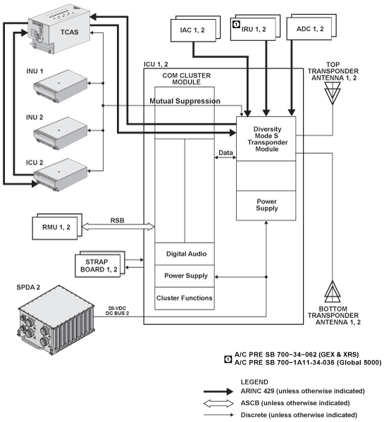
Pre ADS-B Out Option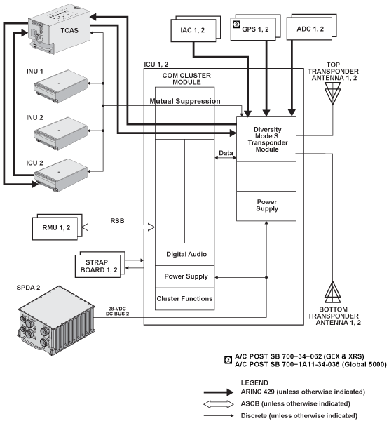
Post ADS-B Out Option
Power Inputs
ATC transponder no. 1 is powered by SPDA 2 DC bus 2.
ATC transponder no. 2 is powered by SPDA 1 battery bus.
05/06/16
System Test
Self-Test
RMU PAST Display
To display RMU PAST, proceed as follows:
- Position the cursor in the ATC transponder window on the radio management unit (RMU) and select transponder 1
- Press and hold the TST button on RMU. The word TEST will appear in the ATC window
- Upon completion of the test, the words ATC PASS in green, or ATC ERROR in red will appear in the ATC window
- When TCAS is installed, SYS TEST is displayed, indicating that both TCAS and the transponder will test. In addition, the TCAS aural warning will annunciate TCAS TEST, TCAS PASS, or TCAS FAIL separately
- It is possible to hold the TST button long enough (8 seconds), to force TCAS and the TCAS traffic display into the maintenance mode. Normal operation can be reestablished by entering a transponder code
- TCAS itself can also be tested with the cursor in the TCAS display window

System Fault Indications
If the squitter function fails in flight, an ATC ERR message will be displayed in yellow at the bottom of the ATC window. This message indicates that the selected TCAS compatible Mode S transponder has lost the ability to operate as part of a collision avoidance system.
If the yellow ATC ERR message is present, perform PAST on the ATC. If the test fails (ATC ERR in red in ATC window), the transponder is not transmitting properly. Select the other side transponder.
If the transponder passes PAST, the squitter function only is inoperative. This only slightly reduces the TCAS reply time. It is preferable to use the other side transponder.

Fault Monitoring/Isolation
The Mode S transponder has extensive self test and performance monitor capability. Each event that is logged in a maintenance log is one of the four categories of events (fail event, install event, troubleshoot event and bench test event).
Fail Event
Fail events occur during normal system operation and are generally a result of an internal failure in the transponder. Fail events cause the module to fail PAST and POST self-test mode and "ATC ERR " annunciator on RMU.
Install Event
Install events occur during normal system operation and are generally a result of a problem outside the transponder, such as installation problem or a failure in a unit which interfaces to the transponder.
Install events do not cause the POST or PAST to fail. Only "Invalid Mode S address" event will cause "ATC ERR" annunciator on RMU.
Troubleshoot Event
Troubleshoot events occur during normal system operation and are designed to aid troubleshooting module problems or failures in the transponder. Troubleshoot events do not cause the module to fail PAST and POST self-test mode and "ATC ERR " annunciator on RMU.
Technical Characteristics
| GENERAL | |
|---|---|
| Receive Mode | 28 VDC, 2A |
| Transmit Mode | 28 VDC, 7A |
| Modes | A, C, S |
| Standby | Receives interrogation signal but cannot reply |
| ATC ON | Replies on Modes S and A, no altitude reporting |
| ATC ALT | Replies on Modes A, C, and S, with altitude reporting |
| TA ONLY | TCAS traffic advisory mode is selected |
| TA/RA | TCAS traffic advisory/resolution advisory mode is selected |
| Transmitter Frequency | 1,090 MHz |
| Transmitter Power | 500 watts peak pulse |
| Receiver Frequency | 1,030 MHz |
| Mutual Suppression | bidirectional, 28 VDC nominal |