07/30/24
Message Overview:
| DDG Reference: | No Go |
| Pilot Action (QRH): | ABNORM 6-4 |
| System Description: | 24-61-00 |
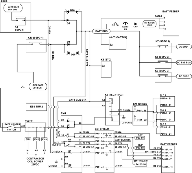
| System Schematic | 24-61-00 [ Global Express ] [ G5000 ] [ Global XRS ] |
| Wiring Diagram: | 24-61-00 [ Global Express ] [ G5000 ] [ Global XRS ] |
Message Description:
Two conditions:
- BATT BUS is not powered
- BATT BUS is isolated by the Primary Logic Cards (PLCs) due to BUS fault detection.
Possible Causes:
- DC Power Center (DCPC) Contactor K3
- DC Power Center (DCPC) Electronic Module 4 (EM4)
- DC Power Center (DCPC) Secondary-Power Distribution Assembly (SPDA) Feeder Assembly BATT BUS Card
- DC Power Center (DCPC) (A63)
- DCPC contactor K5 (ETC)
Troubleshooting Tips:
Advisory Wire/Service Bulletin: None
Forum Articles/Infoservice/Newsletter: None
A K5 (ETC) failure will only show itself when at least one TRU is failed
Quick Links:
| Standard Aircraft Configuration for Maintenance | [ G5000 ] [ Global Express ] [ Global XRS ] AMM12-00-00-867-801 |
| Electrical/Electronic Safety Precautions | [ G5000 ] [ Global Express ] [ Global XRS ] AMM24-00-00-910-801 |
| Electrostatic Discharge Safety Precautions | [ G5000 ] [ Global Express ] [ Global XRS ] AMM24-00-00-910-802 |
| Removal of the DC Power Center (DCPC) | [ G5000 ] [ Global Express ] [ Global XRS ] AMM24-61-00-000-801 |
| Installation of the DC Power Center (DCPC) | [ G5000 ] [ Global Express ] [ Global XRS ] AMM24-61-00-400-801 |
| Operational Test of the DC Power Center (DCPC) | [ G5000 ] [ Global Express ] [ Global XRS ] AMM24-61-00-710-801 |
| Removal of the DC Power Center (DCPC) Secondary-Power Distribution Assembly (SPDA) Feeder | [ G5000 ] [ Global Express ] [ Global XRS ] AMM24-61-37-000-801 |
| Installation of the DC Power Center (DCPC) Secondary-Power Distribution Assembly (SPDA) Feeder | [ G5000 ] [ Global Express ] [ Global XRS ] AMM24-61-37-400-801 |
| Operational Test of the DC Power Center (DCPC) Secondary-Power Distribution Assembly (SPDA) Feeder | [ G5000 ] [ Global Express ] [ Global XRS ] AMM24-61-37-710-801 |
| Removal of the DC Power Center (DCPC) Electronic Modules | [ G5000 ] [ Global Express ] [ Global XRS ] AMM24-61-65-000-801 |
| Installation of the DC Power Center (DCPC) Electronic Modules | [ G5000 ] [ Global Express ] [ Global XRS ] AMM24-61-65-400-801 |
| Operational Test of the DC Power Center (DCPC) Electronic Modules | [ G5000 ] [ Global Express ] [ Global XRS ] AMM24-61-65-710-801 |
| CAIMS PMAT General Instructions | [ G5000 ] [ Global Express ] [ Global XRS ] AMM45-45-00-970-801 |
| Access to Active Faults | [ G5000 ] [ Global Express ] [ Global XRS ] AMM45-45-00-970-802 |
| Access to Stored Faults | [ G5000 ] [ Global Express ] [ Global XRS ] AMM45-45-00-970-803 |
Troubleshooting Recommendations:
- Does this failure only occur when a TRU is failed or off?
- If YES, continue with next step.
- If NO, go to step 3.
- Access DCPC contactor assembly. Do a voltage check for 28 VDC as follows:
From
To
Result
K5-B1
Ground
K5-B2
Ground
- If there is no 28 VDC, replace K5.
- If there is 28 VDC, go to step 5.
- Access DCPC contactor assembly. Power on the A/C and make sure ESS TRU 2 is powered. Do a voltage check for 28 VDC as follows:
From
To
Result
K3-A1
Ground
- If there is 28 VDC, continue with next step.
- If there is no 28 VDC, troubleshoot the wiring between ESS TRU 2 and the DCPC.
- Remove electrical power from the aircraft.
- Do a voltage check for 28 VDC as follows:
From
To
Result
K3-A2
Ground
- If there is voltage, continue with next step.
- If there is no 28 VDC, replace K3.
- Disconnect EM4 connector P407. Do a continuity check as follows:
From
To
Result
P407-12
Ground
P407-15
Ground
- If there is continuity, replace DCPC.
- If there is no continuity, continue with next step.
- Do a continuity check as follows:
From
To
Result
P407-12
K3-A2
P407-15
K3-A2
- If there is continuity, continue with next step.
- If there is no continuity, replace DCPC.
- Remove the BATT SPDA FEEDER CARD. Do a continuity check as follows:
From
To
Result
P407-13
Ground
P407-16
Ground
P407-11
Ground
- If there is continuity, replace DCPC.
- If there is no continuity, continue with next step.
- Do a continuity check as follows:
From
To
Result
P431A-8
P407-13
P431A-9
P407-16
P431A-10
P407-11
- If there is continuity, continue with next step.
- If there is no continuity, replace DCPC.
- Swap the BATT SPDA FEEDER with DC BUS 2 SPDA FEEDER Card. Does the fault follow the card?
- If YES, replace defective SPDA FEEDER Card.
- If NO, replace EM4.
- Do close out.