12/15/20
Message Overview:
| DDG Reference: | None |
| Pilot Action (QRH): | ABNORM 6-6 |
| System Description: | 24-60-00 |
| Schematic Diagram: | 24-61-00 [ Global Express ] [ G5000 ] [ Global XRS ] |
| Wiring Diagram: | 24-61-01 [ Global Express ] [ G5000 ] [ Global XRS ] |
Fault Description:
Fault is reported by DCPC when DC BUS 2 is not powered or DC BUS 2 is isolated by Primary Logic cards due to BUS fault detection.
Possible Causes:
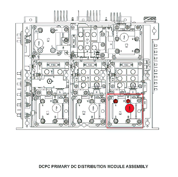
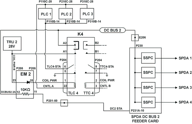
- DC Power Center (DCPC) Contactor (K4)
- DC Power Center (DCPC) Electronic Module (EM2)
- DC Power Center (DCPC) SPDA Feeder Assembly DC BUS 2 Card
- DC Power Center (DCPC) (A63)
Troubleshooting Tips:
Advisory Wire/Service Bulletin: None
Forum Articles/Infoservice/Newsletter: None
Troubleshoot other related electrical system CAIMS messages before.
NOTE: Verify BUS status on both pilot and copilot EMS CDUs.
Quick Links:
| Removal of the DC Power Center (DCPC) | AMM 24-61-00-000-801 [ Global Express ] [ G5000 ] [ Global XRS ] |
| Installation of the DC Power Center (DCPC) | AMM 24-61-00-400-801 [ Global Express ] [ G5000 ] [ Global XRS ] |
| Removal of the DC Power Center (DCPC) Secondary-Power Distribution Assembly (SPDA) Feeder | AMM 24-61-37-000-801 [ Global Express ] [ G5000 ] [ Global XRS ] |
| Installation of the DC Power Center (DCPC) Secondary-Power Distribution Assembly (SPDA) Feeder | AMM 24-61-37-400-801 [ Global Express ] [ G5000 ] [ Global XRS ] |
| Removal of the DC Power Center (DCPC) L-Series Contactor | AMM 24-61-53-000-801 [ Global Express ] [ G5000 ] [ Global XRS ] |
| Installation of the DC Power Center (DCPC) L-Series Contactor | AMM 24-61-53-400-801 [ Global Express ] [ G5000 ] [ Global XRS ] |
| Removal of the DC Power Center (DCPC) Electronic Modules | AMM 24-61-65-000-801 [ Global Express ] [ G5000 ] [ Global XRS ] |
| Installation of the DC Power Center (DCPC) Electronic Modules | AMM 24-61-65-400-801 [ Global Express ] [ G5000 ] [ Global XRS ] |
Troubleshooting Recommendations:
- In CAIMS, SYSTEM DIAG, ATA 24, DC POWER CENTER DCPC_A, LRU TEST, DC POWER DISTRIBUTION page 3. Check the status of TLC 4.
- If status is closed, continue with next step.
- If status is open continue with step 3.
- Open DCPC contactor assembly cover and access K4. Check for 28 VDC input on A1 and output on terminal A2.
- If voltage is present on A1 but not on A2, replace contactor K4.
- If voltage is present on A1 and A2 continue with step 5.
- Shut down aircraft power, disconnect P204 from contactor K4 and apply power to the aircraft. Make sure 28 VDC is present on pin 1.
- If 28 VDC is not present, continue with step 4.
- If 28 VDC is present, replace contactor.
- Replace Electronic Module EM2.
- If system checks are good, do close out.
- If fault remains, continue with next step.
- Swap SPDA Feeder Assembly DC BUS 2 (Card 2) Card with DC BUS 1 (card 1).
- If fault follows, replace faulty Feeder card.
- If fault remains, replace EM2 if not already done.
- If fault remains and EM2 has been replaced, continue with next step.
- Replace DCPC.
- Do close out.